Operation specifications, Din connector specifications, Mounting on a dynamics cart – PASCO CI-6558 Rev A ACCELERATION SENSOR User Manual
Page 3: Maximum usable acceleration: ± 5 g or 50 m/s, Se ns or po sit ion
012-06361C
Acceleration Sensor
3
Operation Specifications:
• Maximum usable acceleration: ± 5 g or 50 m/s
2
• Sensor Output: 1 V/g
• Accuracy: 0.01 g or 0.1 m/s
2
• Resolution: 0.001 g or 0.01 m/s
2
• Alignment error of the acceleration sensing element:
±1° (Alignment error is defined as the difference
between the true and indicated axis of sensitivity.)
• Absolute maximum acceleration without damaging
the sensing element: 1000 g for 0.5 ms
4
Orient the sensor so the + arrow on the label is
pointing toward the ground (Figure 3b).
5
Click
beside the High Value dialog box.
6
Rotate the sensor 180° around its major axis so the
– arrow points toward the ground (Figure 3b).
7
Click
beside the Low Value dialog box.
8
Click OK. The Acceleration Sensor is now calibrated.
DIN Connector Specifications
1: analog output (+), 0 to 10 V
2: analog output (-), signal ground
3: (no connection)
4: + 5 V DC power
5: power ground
6: +12 V DC power
7: -12 V DC power
8: (no connection)
1
4
3
5
2
6
7
8
FAST
SLOW
SENSOR
RESPONSE
a
5
g
TARE
Figure 3. Positions of the Acceleration Sensor
during the calibration procedure.
FAS
T
SLO
W
SEN
SO
R
RES
PO
NSE
a
5
g
TA
RE
A
CC
E
LE
R
ATIO
N
S
EN
SO
R
CI-6558
a
5
g
D
IR
E
C
T
IO
N
O
F
A
C
C
E
L
E
R
A
T
IO
N
-
+
S
E
N
S
O
R
P
O
S
IT
IO
N
FA
S
T
S
L
O
W
S
E
N
S
O
R
R
E
S
P
O
N
S
E
a
5
g
TA
R
E
AC
CE
LE
RA
TIO
N
SE
NS
OR
CI-
655
8
a
5
g
DIR
EC
TIO
N O
F A
CC
EL
ER
AT
ION
-
+
SE
NS
OR
PO
SIT
ION
a
b
Press the
tare button
Rotate
180°
Calibrating the Acceleration Sensor
The Acceleration Sensor is factory calibrated and is
accurate to about 0.05 g or 0.5 m/s
2
. For most
experiments, no further calibration is required. However,
the following calibration procedure may be performed to
maximize the Acceleration Sensor's accuracy.
Maintaining the Direction of Sensitivity
The sensing unit of the Acceleration Sensor is oriented so
that the line of greatest sensitivity follows the arrow
indicating the direction of acceleration (Figure 2).
Experiments should be conducted with the arrow on the
label of the Acceleration Sensor oriented along the same
line as the direction of the acceleration to be measured.
1
Double click the Acceleration Sensor icon (
) in
the setup window of Data Studio then click the Cali-
bration tab.
2
In the Calibration dialog, enter 1.000 in the High
Value dialog box in the pop-up menu, and -1.000 in
the Low Value dialog box.
3
Place the sensor flat on a level surface with the arrow
indicating direction of sensitivity parallel to the
ground (Figure 3a) and press the tare button.
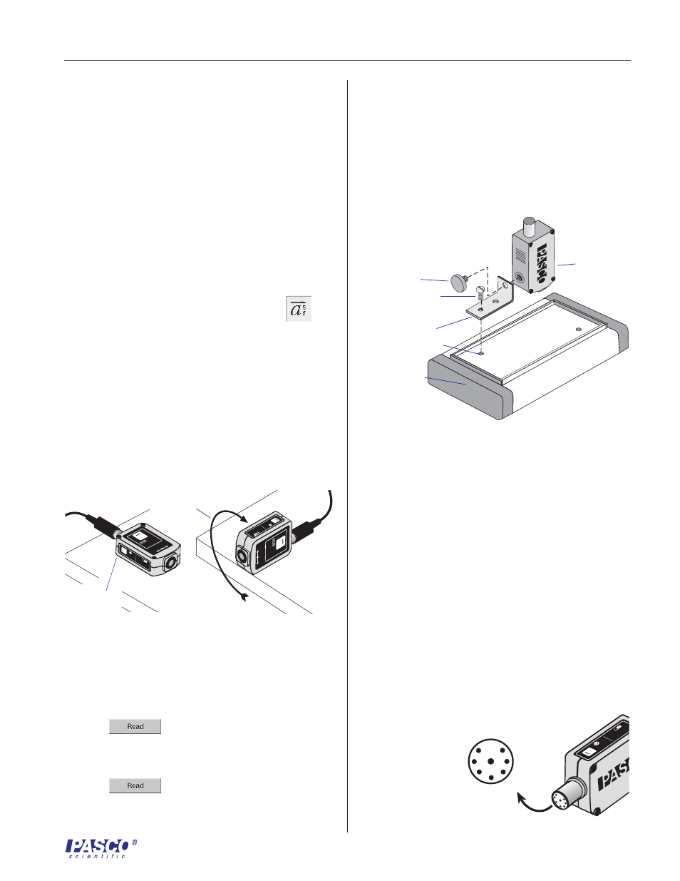
Mounting on a Dynamics Cart
Figure 4. Mounting the Acceleration Sensor to the
bed of the Dynamics Cart.
thumbscrew
Dynamics Cart
bracket
bolt
threaded connector
➤
➤
➤
➤
➤
Note: For a detailed description of the
calibration process, access the Data Studio Help
menu and click Setup Information, Setting up a
sensor.
Acceleration
Sensor