Setup procedure – PASCO CI-6558 Rev A ACCELERATION SENSOR User Manual
Page 2
012-06361C
2
Acceleration Sensor
2
Open the Data Studio program. In the setup window,
click and drag the analog plug icon (
) to the
analog channel icon (
) that corresponds to the
port the Acceleration Sensor is plugged into.
3
Select
from the pop-up
menu.
4
Open a display window, such as the Graph
display, by dragging and dropping the appropriate
display icon (
) to the Acceleration Sensor
icon (
).
Setup Procedure
Setting Up Data Studio
1
Connect the Acceleration Sensor to any analog
channel on the computer interface box with interface
cable (Figure 1a),
or
insert the DIN plug of the Acceleration Sensor into
the jack of any analog channel on the computer
interface box (Figure 1b).
➤
➤
➤
➤
➤
Note: Open additional display windows by
following the procedure in steps 4 and 5.
5
To select units of g or m/s
2
for the display double click
the icon (
) and select the Measurements tab.
To select units of g, click the check box next to
Acceleration (g)
.
To select units of m/s
2
, click the check box next to
Acceleration, A (m/s/s)
.
6
If accelerations of less than 1 g or 10 m/s
2
are to be
measured, the sensitivity may be increased to
medium (10X gain) as follows:
Double-click on the Acceleration Sensor icon
(
) in the setup window to open the Acceleration
Sensor dialog box. Click on the arrow under the
Calibration tab for Sensitivity and select Med (10x)
in the pop-up menu.
7
The default sampling rate is 10 samples/second.
Change the sampling rate, if required, by clicking the
General tab and using the - and + buttons to select the
desired sampling rate.
1
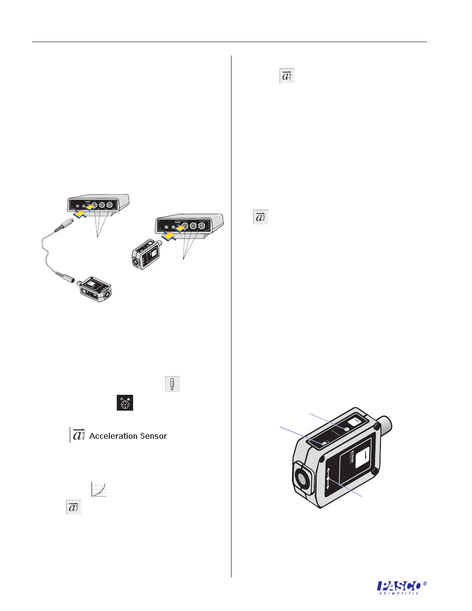
Set the filter switch to slow for most applications. Set
it to high for collision experiments or similar
mechanical experiments (Figure 2).
2
Press the tare button to set the sensor to 0 under the
current conditions (Figure 2).
Adjusting the Acceleration Sensor
Figure 2. Sensor setup controls and arrow indicator
of the direction of sensitivity.
Interface
500
1
2
GAIN=1,10:ISOLATED
GAIN =
1,10: REF TO GND
GAIN =
1: REF TO GND
A
s
C
ON
ANALOG CHANNELS
B
n
DIGITAL CHANNELS
ScienceWorkshop
™
P
R E S S
T
O
L O
G
®
F
A
S
T
S
L
O
W
S
E
N
S
O
R
R
E
S
P
O
N
S
E
a
5
g
T
A
R
E
ACC
EL
ERA
TIO
N
SE
NS
OR
CI
-65
58
a
5
g
DI
RE
CT
IO
N
OF
A
CC
EL
ER
AT
IO
N
-
+
SE
NS
OR
PO
SIT
IO
N
P
R E S S
T
O
L O
G
Interface
500
®
1
2
GAIN=1,10:ISOLATED
GAIN =
1,10: REF TO GND
GAIN =
1: REF TO GND
A
s
C
ON
ANALOG CHANNELS
B
n
DIGITAL CHANNELS
ScienceWorkshop
™
FAS
T
SLO
W
SEN
SOR
RES
PON
SE
a
5
g
TAR
E
A
C
C
E
L
E
R
A
T
IO
N
S
E
N
S
O
R
C
I-6
5
5
8
a
5
g
D
IR
E
C
T
IO
N
O
F
A
C
C
E
L
E
R
A
T
IO
N
-
+
S
E
N
S
O
R
P
O
S
IT
IO
N
FAST
SLOW
SENSOR
RESPONSE
a
5
g
TAR
E
A
CCELERATION
SENSOR
C
I-6
5
5
8
a
5
g
DIRECTION OF ACCELERATION
-
+
SENSOR
POSITION
A
b
Plug into
any analog
channel.
Plug into any
analog
channel.
Figure 1. Connecting the Acceleration Sensor to the
computer interface.
a
filter switch:
fast or slow
tare button
indicator of direction
of sensitivity and
sensor position