Mounting on an experimental apparatus, Din connector specifications, Specifications – PASCO CI-6556 CURRENT SENSOR User Manual
Page 3: Ior i, Equipment setup
012-06431B
Current Sensor
3
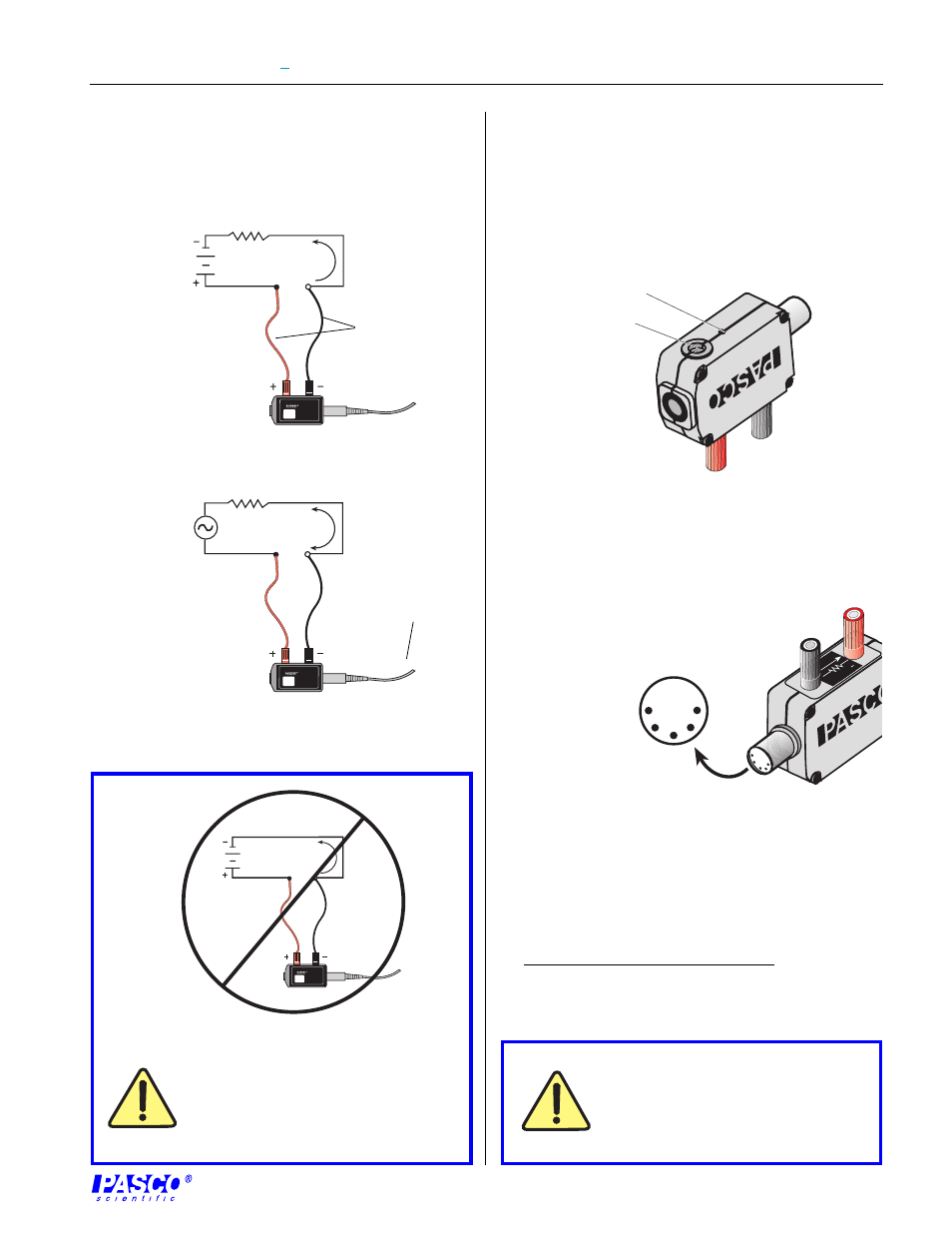
Mounting on an Experimental Apparatus
➀
Use the 1/4–20 threaded screw connector located on
the bottom of the sensor box to secure the Current Sensor
to an experimental apparatus (Figure 6). The alignment
hole fits over an alignment pin included on some PASCO
apparatuses.
The exclamation point within an
equilateral triangle is intended to alert
the user of the presence of important
operating and maintenance (servicing)
instructions in the literature
accompanying the device.
Equipment Setup
➀
Break the circuit at the point the current flow is to be
measured and insert the Current Sensor using standard
banana plug connectors or other suitable means
(Figure 5).
Warning! Do not connect the Current
Sensor directly across a voltage source
or unloaded ciruit. Connecting to a
source that causes a current of greater
than 1.5 A to flow will permanently
damage to the sensor.
Figure 5. Equipment Setup for measuring current across a
circuit with a DC (a) or AC (b) power source.
b
a
patch cords
to computer interface
Figure 6. Connections for mounting on some PASCO
experimental apparatuses.
1/4–20 threaded
screw connector
alignment hole
DIN Connector Specifications
1: analog output (+),
-1.5 to 1.5 V
2: analog output (-),
signal ground
3: (no connection)
4: (no connection)
5: (no connection)
Specifications:
resolution: 5 mA (1X gain in Science Workshop)
0.5 m
Α (
10X gain in Science Workshop)
maximum current input: 1.5 A*
maximum differential voltage: 1.5 V*
maximum common mode voltage: ± 10 V*
*DC or AC RMS (root mean square)
CURRENT
SENSOR
CI-6556
MAX CURRENT: ±1.5A
I
I
or
I
CURRENT
SENSOR
CI-6556
MAX CURRENT: ±1.5A
I
CURRENT
SENSOR
CI-6556
MAX CURRENT: ±1.5A
I
I
1
4
3
5
2
CURRENT
1.00
Ω
+
4