Mounting on an experimental apparatus, Din connector specifications – PASCO CI-6628 INFRARED SENSOR User Manual
Page 3
012-06915B
Infrared Sensor
3
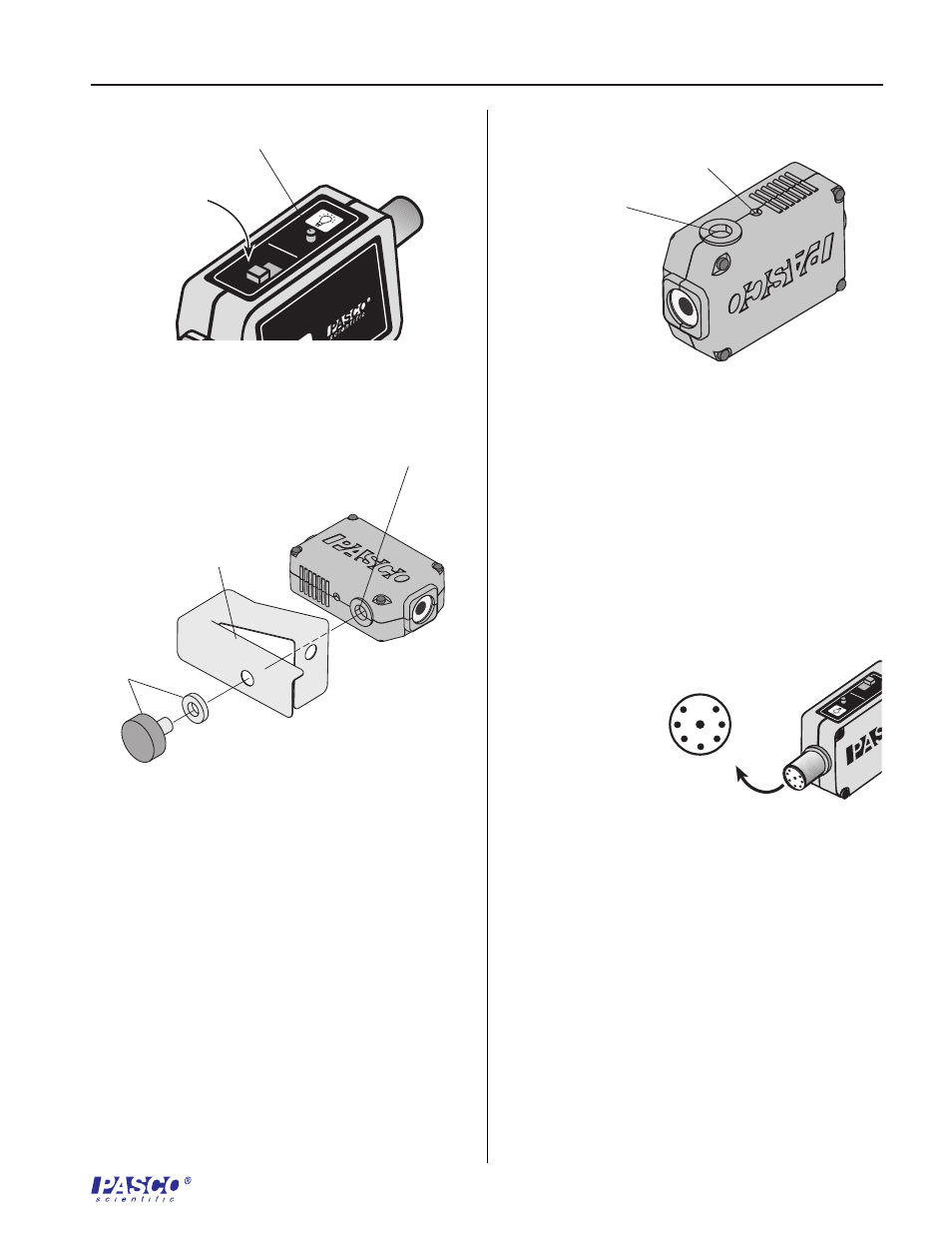
Note the orientation of components as illustrated in
Figure 3. Mount the shutter bracket to the Infrared
Sensor unit, with the included hardware, as shown.
Do not over tighten thumbscrew.
Mounting on an Experimental Apparatus
Use the 1/4-20 threaded connector located on the
bottom of the sensor box to secure the Infrared
Sensor to an experimental apparatus (Figure 4).
The alignment hole fits over an alignment pin
included on some PASCO apparatuses.
DIN Connector Specifications
1: analog output (+), -10 to +10 V
2: analog output (-), signal ground
3: (no connection)
4: + 5 V DC power
Figure 3
Installation of Shutter Bracket
(Figure 2). The correct gain setting is the one
for which the intensity levels on the display
vary appropriately for measuring the relative
light intensity changes in your experiment.
Using the Shutter Bracket
10
1
100
GAIN
TARE
1
4
3
5
2
6
7
8
10
1
100
GAIN
TARE
INFRARED SENSOR
I 6
628
Adjust the gain
for the light
conditions
Tare
button
Figure 4
Mounting connector and alignment hole
shutter bracket
1/4-20 threaded
connector
1/4-20
thumb-
screw
and washer
alignment hole
1/4-20 threaded
connector
Figure 2
Setting the Gain On the Infrared Sensor