Equipment, Operation, Computer interface • science workshop – PASCO CI-6628 INFRARED SENSOR User Manual
Page 2
Infrared Sensor
012-06915B
2
Interface
500
1
2
GAIN=1,10:ISOLATED
GAIN =
1,10: REF TO GND
GAIN =
1: REF TO GND
A
s
C
ON
ANALOG CHANNELS
B
n
DIGITAL CHANNELS
ScienceWorkshop
P
R E S S
T
O
L O
G
®
10
1
100
GAIN
TARE
INFRARED SENSOR
CI-6628
output of the sensor to a level appropriate for the
experiment being performed. Gain settings of 1X,
10X and 100X are provided. The gain settings on
the sensor coupled with the user selectable gain of
the PASCO Computer Interface allow a very broad
range of measurements to be made with the
Infrared Sensor.
The TARE switch located on the top of the sensor
allows the output of the sensor to be zeroed. This is
particularly useful at high gain settings where small
voltage offsets may interfere with measurements.
The shutter provided with the sensor has two
functions. The tab on the front edge is used to give
constant spacing between the sensing element and
a hot object when performing comparative radiant
energy measurements. The spring loaded shutter
keeps unwanted radiated energy from heating the
sensing element before a measurement is taken.
Equipment
INCLUDED
• Infrared Sensor unit
• 1/4-20 X .375” thumbscrew (washer
included)
• shutter bracket
• cable with DIN connectors
ADDITIONAL REQUIRED
• computer (PC or Macintosh)
• Science Workshop
®
computer interface
• Science Workshop
®
software version 2.2 or
higher
Spare parts are available as follows:
Item
Part Number
8-pin DIN cable
514-06329
.250” I.D. washer
615-011
1/4-20 X .375” thumbscrew 617-008
shutter bracket
648-06954
Operation
Note: This instruction sheet was written assuming
that the user has a basic familiarity with
Science Workshop and has access to the User’s
Guide for Science Workshop. Users can gain
basic skills by working through the tutorial within
Science Workshop. Another useful resource is the
Quick Reference Card for Science Workshop.
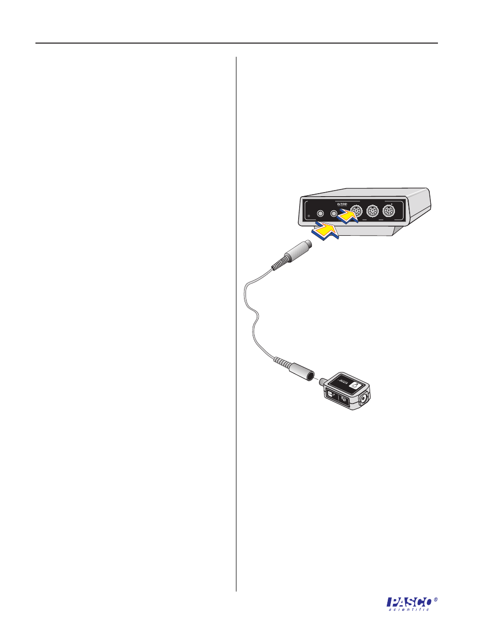
Setting up the Equipment
1. Connect the Infrared Sensor unit to analog
channel A, B, or C of the Science Workshop
computer interface box using the cable with
the DIN connectors (Figure 1). Alternatively,
the unit can be plugged directly into the
analog channel jack without using the cable.
2. Select the appropriate gain setting on the
sensor box for the light levels to be measured
Figure 1
Connecting the amplifier box to the interface box