PASCO CI-6718 ELVIS Adapters User Manual
Page 2
ELVIS Adapters
012-08925A
2
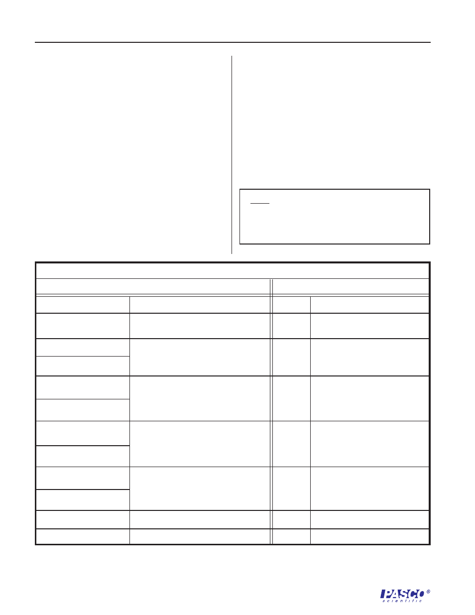
Chart: Connection of Analog ScienceWorkshop Sensors
ELVIS I/O
Analog Adapter I/O
ACH0+
Analog channel #0 Positive Sense
AIN+
Positive Sensor Analog Input
ACH0-
Analog channel #0 Negative Sense
AIN-
Negative Sensor Analog
Input Port
DC Power Supplies
+ 5 V Power Supply Output
+5 V
+ 5 V Sensor Power Input
+5 V
DC Power Supplies
Power Ground
PGND
Sensor Power Ground
GND
Variable Power Supplies
+ 12 V Power Output.*
+12V
+12V Sensor Power Input
SUPPLY +
Variable Power Supplies
- 12 V Power Output.*
-12V
-12V Sensor Power Input
SUPPLY -
N/C
No Connection
AOUT
Analog Output **
3. Steady the DIN connector with one hand and
plug the desired analog sensor into the adapter.
4. Create a Virtual Instrument (VI) using
LabVIEW software to collect and analyze data
with the sensor.
Using Digital Sensors
1. Plug the digital adapter into a prototyping
board.
2. Connect wires from the inputs/outputs of the
adapter to the desired inputs and outputs.
(Reference the appropriate connection chart.)
Please note that the two sets of pins nearest the
stereo jacks are not electrically connected. They
simply provide additional mechanical support
for the adapter.
Note: If you are plotting the input from an
unused channel, its output will tend to follow
that of the last input in the multiplex scan order
unless its inputs are shorted.
* Set the dials for the variable power supplies to "manual" and change the values to +/- 12 V.
* *Usually not connected.
3. Steady the adapter with one hand and plug the
desired digital sensor into the adapter.
The adapter will accommodate:
- One Motion Sensor or Rotary Motion Sensor
- Two Photogates, Smart Pulleys, Time of
Flight Pads, or Nuclear Sensors
4. Create a Virtual Instrument (VI) using
LabVIEW software to collect and analyze data
with the sensor.