PASCO ME-6829 Mini Launcher Ballistic Pendulum User Manual
Page 8
®
M i n i L a u n c h e r B a l l i s ti c P e n d u l u m
E x p e r i m e n t 1 : I n e l a s t i c C o l l i s i o n s
8
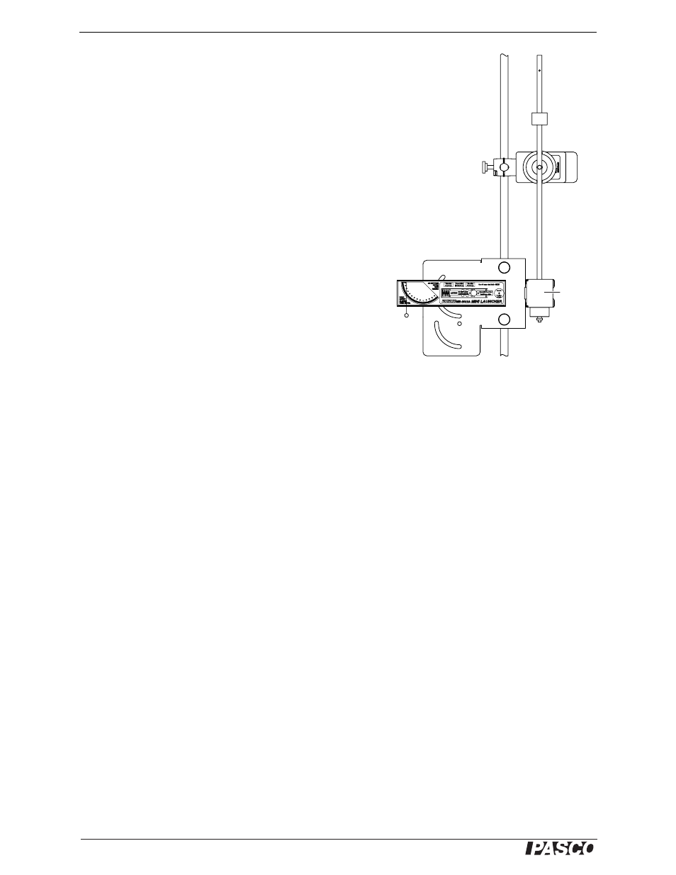
Part B: Partially Inelastic Collision (Ball Bounce)
1.
Remove
the pendulum from the RMS. Reattach the pendu-
lum with the bumper facing the launcher. There should be a
gap of a few centimeters between the end of the launcher and
the bumper.
2.
Predict what will happen. Will the maximum angular dis-
placement in this part be greater or less than in the maximum
displacement in Part A? _____________
3.
Guess the maximum angle that the pendulum will swing to.
Record your prediction here. ______________
4.
Start data collection.
5.
Pull the trigger to launch the ball so it hits the pendulum and
bounces off.
6.
After the pendulum swung out and back, stop collection.
7.
Record the maximum angular displacement of the pendulum
here. ___________
Analysis
1.
Was the maximum angular displacement in Part B greater or less than in
Part A? ______________
2.
Was your prediction in Part B step 2 correct? ______________
3.
Create a graph of angular velocity versus time showing the data from parts A and
B. Which type of collision (completely inelastic or partially inelastic) resulted in
the greater maximum velocity? ______________
4.
Explain qualitatively how maximum velocity is related to maximum angular dis-
placement.
________________________________________________________________
________________________________________________________________
________________________________________________________________
________________________________________________________________
________________________________________________________________
________________________________________________________________
Bumper
side
Figure 1.3: Set-up for Part B