PASCO ME-6829 Mini Launcher Ballistic Pendulum User Manual
Page 14
®
Mini Launcher Ballistic Pendulum
Experiment 3: Conservation of Momentum and Energy
14
2.
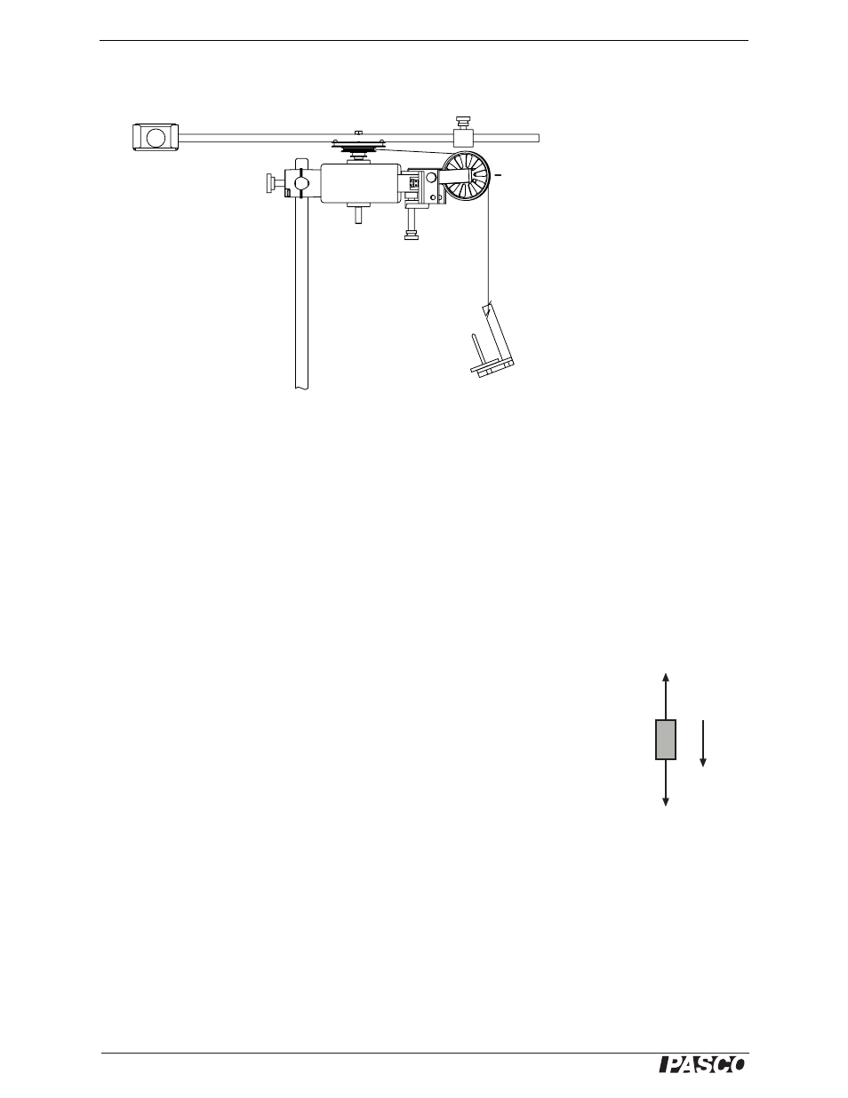
Clamp the RMS on the mounting rod so that the pendulum can rotate in a hori-
zontal plane (see Figure 3.3).
Figure 3.3: Setup for determining rotational inertia
3.
Clamp a pulley to the RMS and set up a string and hanging mass (approximately
20 g to 30 g) as shown in Figure 3.3. Wind the string a few times around the mid-
dle step of the three-step pulley. Adjust the angle and height of the clamped-on
pulley so that the string will unwind and run over the pulley with as little friction
as possible.
Procedure
1.
Start data collection.
2.
Release the hanging mass.
3.
After the string has unwound from the three-step pulley, stop data collection.
4.
Determine the angular acceleration of the pendulum (
α) from the slope of the
angular velocity versus time graph.
α = _____________________
5.
Measure the radius of the middle step of the three-step pulley.
R
pulley
= _____________________
6.
Measure the mass of the hanging mass. m = _____________________
7.
Calculate the acceleration (a) of the hanging mass.
a =
α R
pulley
8.
Calculate the tension in the string (F
T
). Since the hanging mass is accelerating,
the string tension is not the weight of the mass. Writing Newton’s 2nd Equation
for the free-body diagram in Figure 3.4 yields:
ma = mg
− F
T
where g = 9.8 m/s
2
.
F
T
= _____________________
Hanging
mass
Clamped-on
pulley
a
mg
F
T
Figure 3.4: Free-body
diagram of hanging
mass