A.O. Smith VB/VW-500 User Manual
Page 9
9
WATER TEMPERATURE LIMIT CONTROLS
The “V(B/W)” models incorporate an outlet water probe consisting
of two limit controls:
1. An adjustable automatic high limit control that can be set as
high as either 210°F (99°C) or 235°F (113°C), depending on
the application.
2. A fixed manual high limit (ECO), factory set at 244°F (118°C). If
the manual reset should open due to high temperature, the
gas valves will close and the unit will go into lockout. If lockout
occurs, push the SELECTION button on the UIM to restart the boiler.
ON/OFF SWITCH
The ON/OFF Switch is a single-pole, single-throw rocker switch.
This switch provides 120V from the line source to the boiler.
CIRCULATING PUMP
HOT WATER SUPPLY BOILER-VW, the circulating pump is
integral to the VW models. This pump has been lubricated at
the factory, and future lubrication should be in accordance
with the motor manufacturer’s instructions provided as a
supplement to this manual.
FOR HOT WATER HEATING BOILERS-VB MODELS, the
circulating pump is NOT provided on standard models (optional)
and must be obtained and installed in the field.
NOTE: If a system pump is to be installed on a VB
model, the maximum rating of the pump motor must
not exceed 1 hp.
REMOTE PROBE
FOR HOT WATER SUPPLY BOILERS-VW models, a remote
probe is supplied with each hot water supply boiler. The inlet water
temperature and the tank temperature are displayed separately
on the default menu screen.
Note: The remote probe must be designated as the controlling probe
using dipswitch “4” on MCB before it can be used for VW hot water
supply applications, see page 29 (MCB -Ten Position Dip Switch).
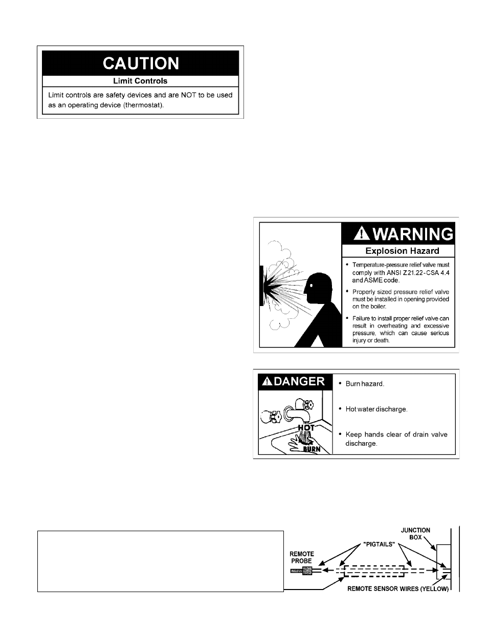
“Pigtails” of field-supplied yellow wires located in the rear of
the unit in the junction box should be spliced to “pigtails” of
remote probe and connected in the junction box. See Figure 7
for probe installation.
FOR HOT WATER HEATING BOILERS-VB models, a remote
probe is supplied due to the various types of systems and operating
conditions. A remote probe can be used as an option to control
loop temperature and unit staging. Additionally, the inlet
temperature probe can be used as the loop thermostat in some
heating applications. The remote probe connects to designated
wires in the junction box at the rear of the boiler, refer to the PROBE
INSTALLATION section. Do not operate this boiler using the
internal high limits only; use a remote probe or operating
thermostat to control system temperatures.
LOW WATER CUTOFF (Optional)
If low water detection is required by the authorities having
jurisdiction, a low water cutoff switch should be installed next to
the boiler in the outlet water line as shown in Figure 13. The switch
should receive periodic (every six months) inspection to assure
proper operation. A Low Water Cutoff device of the float type should
be flushed every six months.
SAFETY RELIEF VALVE
The purpose of a safety relief valve is to avoid excessive pressure
or temperature into the steam range which may cause scalding at
fixtures, tank explosion, system damage, or boiler damage.
To avoid scalding or water damage, a drain line must be
connected to a safety relief valve to direct discharge to a safe
FIGURE 7. REMOTE PROBE INSTALLATION.
Encase field-supplied wires between remote probe and junction box with
1/2" field supplied conduit. "Pigtails" of field-supplied wires should be
spliced to "pigtails" of remote probe. This conduit and wiring should be
separate from any other conduit/wiring to guard against EMI
(electromagnetic interference).