Gas connections – A.O. Smith VB/VW-500 User Manual
Page 20
20
This is accomplished by changing two dipswitch settings on
the MCB. First, dipswitch “4” must be set to the “ON” position
to designate the remote probe as the controlling probe.
Second, dipswitch “1” must be set to the “OFF” position to
limit the maximum remote probe temperature for VW
applications. Also, make sure dipswitch “1” is set to the
“OFF” position, which sets the outlet temperature for VW
applications. Failure to do this will void the warranty. If the
remote probe is not designated as the controlling probe, the
unit will be controlled by the inlet probe and will not use the
desired tank temperature as its base.
Refer to Connection Diagram, Figure 18, in order to connect
the remote probe to the boiler, see page 29 for Dipswitch
positions.
GAS CONNECTIONS
Make sure the gas on which the boiler is to operate is the
same as that specified on the rating plate. Do not install
the boiler if equipped for a different type of gas. Consult
your gas supplier.
This boiler is not intended to operate at gas supply
pressure other than shown on the rating plate. A lock-up
or positive shut-off type regulator must be installed in the
gas supply line. Exposure to higher gas supply pressure
may cause damage to gas valves which can result in fire
or explosion. If overpressure has occurred such as through
improper testing of gas lines or emergency malfunction of
the supply system, the gas valves must be checked for
safe operation. Make sure that the outside vents on the
supply regulators and the safety vent valves are protected
against blockage. These are parts of the gas supply system,
not the boiler. Vent blockage may occur during ice build-up
or snowstorms.
The boiler must be isolated from the gas supply piping
system by closing its main manual gas shut-off valve during
any pressure testing of the gas supply piping system at
test pressures equal to or less than 1/2 psig.
Disconnect the boiler and its main manual gas shut-off valve
from the gas supply piping during any pressure testing of the
gas supply system over 1/2 psig. The gas supply line must be
capped when not connected to the boiler.
It is important to guard against gas valve fouling from
contaminants in the gas ways. Such fouling may cause
improper operation, fire or explosion. If copper supply
lines are used they must be approved for gas service.
When local codes require a main manual shut-off valve
outside the boiler jacket, a suitable main manual shut-
off valve must be installed in a location complying
with those codes.
Before attaching the gas line be sure that all gas pipe is clean on
the inside.
To trap any dirt or foreign material in the gas supply line,
a dirt leg (sometimes called drip leg) must be incorporated
in the piping. The dirt leg must be readily accessible and
not subject to freezing conditions. Install in accordance
with recommendations of serving gas supplier. Refer to
national fuel gas code, ANSI Z223.1 or CAN/CSA – B149.1,
and current addenda.
Size of gas supply piping may be larger than heater connection on
installations where a significant run of piping is required.
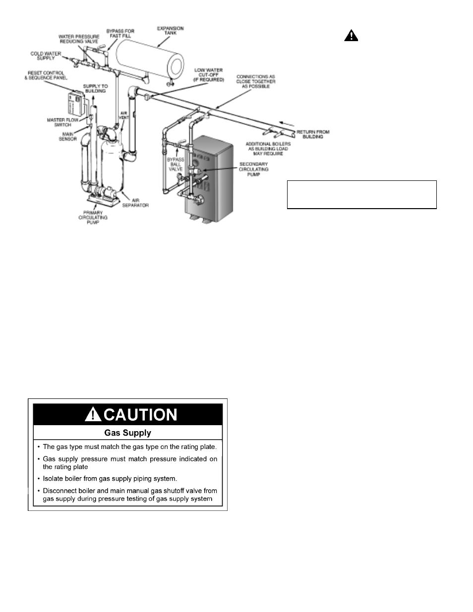
FIGURE 13. TYPICAL PRIMARY, SECONDARY PIPING.
• INSTALL IN ACCORDANCE WITH ALL LOCAL CODES.
• WHEN BLOW DOWN VALVE IS REQUIRED, INSTALL
IN PLACE OF THE DRAIN VALVE SHOWN.
DANGER
TEMPERATURE SETTING SHOULD NOT
EXCEED SAFE USE TEMPERATURE AT
FIXTURES. IF HIGHER PREHEAT
TEMPERATURES ARE NECESSARY TO OBTAIN
ADEQUATE BOOSTER OUTPUT, ADD AN ANTI-
SCALD VALVE FOR HOT WATER SUPPLIED TO
FIXTURES, SEE TABLE 11.