Wiring – A.O. Smith VB/VW-500 User Manual
Page 22
22
To prevent damage, care must be taken not to apply too much
torque when attaching gas supply pipe to boiler gas inlet.
Fittings and unions in the gas line must be of the metal to metal type.
Apply joint compounds (pipe dope) sparingly and only to the male threads
of pipe joints. Do not apply compound to the first two threads. Use
compounds resistant to the action of liquefied petroleum gases.
GAS SUPPLY LINE SIZING
The gas piping installation must be capable of supplying the
maximum probable gas demand without excessive pressure
loss. Depending on local practices, the ALLOWABLE
PRESSURE LOSS between the gas meter, or service regulator
and each appliance is generally 0.3 or 0.5 inches of water
column (0.075 or 0.124kPa).
For single boiler installation, refer to Table 6 to size iron pipe or
equivalent gas supply line size to be used with single unit.
For multiple boiler installation or installations of a single boiler with
other gas appliances, please refer to tables 7 and 8 to size iron
pipe or equivalent gas supply line. These tables are taken from the
current ANSI Z223.1 NATIONAL FUEL GAS CODE, or CAN/CSA
– B149.1 - 00 (and current addenda):
•
Table 7 is based on a pressure drop of 0.5 inches water column
(0.124kPa), and a gas with a specific gravity of 0.60 and a heating
value of 1,000 BTU/ft
3
, approximately that of Natural Gas.
•
Table 8 is based on a pressure drop of 0.5 inches water column
(0.124kPa), and a gas with a specific gravity of 1.53 and a heating
value of 2,500 BTU/ft
3
, approximately that of Propane Gas.
No additional allowance is necessary for an ordinary number of fittings.
Where it is necessary to use more than the average number of fittings
(i.e., elbows, tees and valves in gas supply line) use a pipe larger than
specified to compensate for increased pressure drop.
TABLE 6.
SINGLE UNIT INSTALLATION, SUGGESTED GAS PIPE SIZING.
MAXIMUM EQUIVALENT PIPE LENGTH (IN FEET).
Btu
1-1/4"
1-1/2"
2"
2-1/2"
Input
Nat.
Prop.
Nat.
Prop.
Nat.
Prop.
Nat.
Prop.
500,000
40
90
80
200
—
—
—
—
750,000
10
40
40
90
125
—
—
—
1,000,000
—-
20
20
50
70
175
175
—
Natural gas 1000 Btu/ft^
3
, 0.60 specific gravity @ 0.3 in. w.c. pressure drop.
Propane gas 2500 Btu/ft^
3
, 1.50 specific gravity @ 0.3 in. w.c. pressure drop.
Table 6 shows the maximum equivalent gas pipe length for a single
unit installation. It does not take into account other appliances that
may be connected to the gas line. For installation of multiple units,
or instances where several appliances are connected to the same
line, use Tables 7 and 8 for proper sizing.
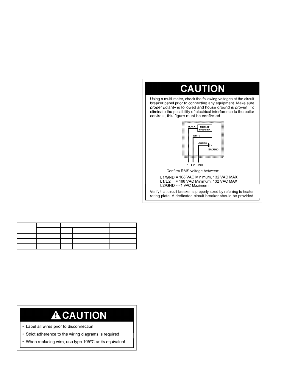
WIRING
Label all wires prior to disconnection when servicing controls.
Wiring errors can cause improper and dangerous operation.
Verify proper operation after servicing. Strict adherence to
the wiring diagrams is required to prevent constant pump
operation when the system controller is satisfied. Otherwise
the warranty is void as stipulated in the limited warranty in
this installation manual.
If any of the original wire, as supplied with the appliance,
must be replaced, it must be replaced with type 105°C wire
or its equivalent.
There are five (5) electrical connections that must be made
for the unit to operate correctly:
1. BLACK (No Stripe) 120V HOT (L1)
2. WHITE 120V NEUTRAL (L2)
3. GREEN GROUND
4. (2) TANK PROBE OR (2) RED/GREEN 24V THERMOSTAT.***
*** Either the tank probe or the 24V thermostat connections
are to be made, but not both.
These connections shall be made at the rear of the unit
where a junction box is provided. AN ELECTRICAL
GROUND IS REQUIRED TO REDUCE THE RISK OF
ELECTRIC SHOCK OR POSSIBLE ELECTROCUTION. A
GROUND SCREW IS PROVIDED IN THIS JUNCTION BOX.
NOTE: Tank probes are not provided on VB models, it is
required that a system/operating temperature controller
(field supplied) be installed to regulate loop or system
temperatures. Two yellow wires are provided in the rear
junction box for this connection. Do not operate this
boiler without system or operating control.
DO NOT connect both sets of wires to a control. If the Tank Probe
is being used, cap securely the Red/Green wires at the junction
box. Do not connect the Red/Green wires together.
Refer to the Connection Diagram, see Figure 17, and to
the Schematic Diagram, see Figure 18.