Features – A.O. Smith VB/VW-500 User Manual
Page 8
8
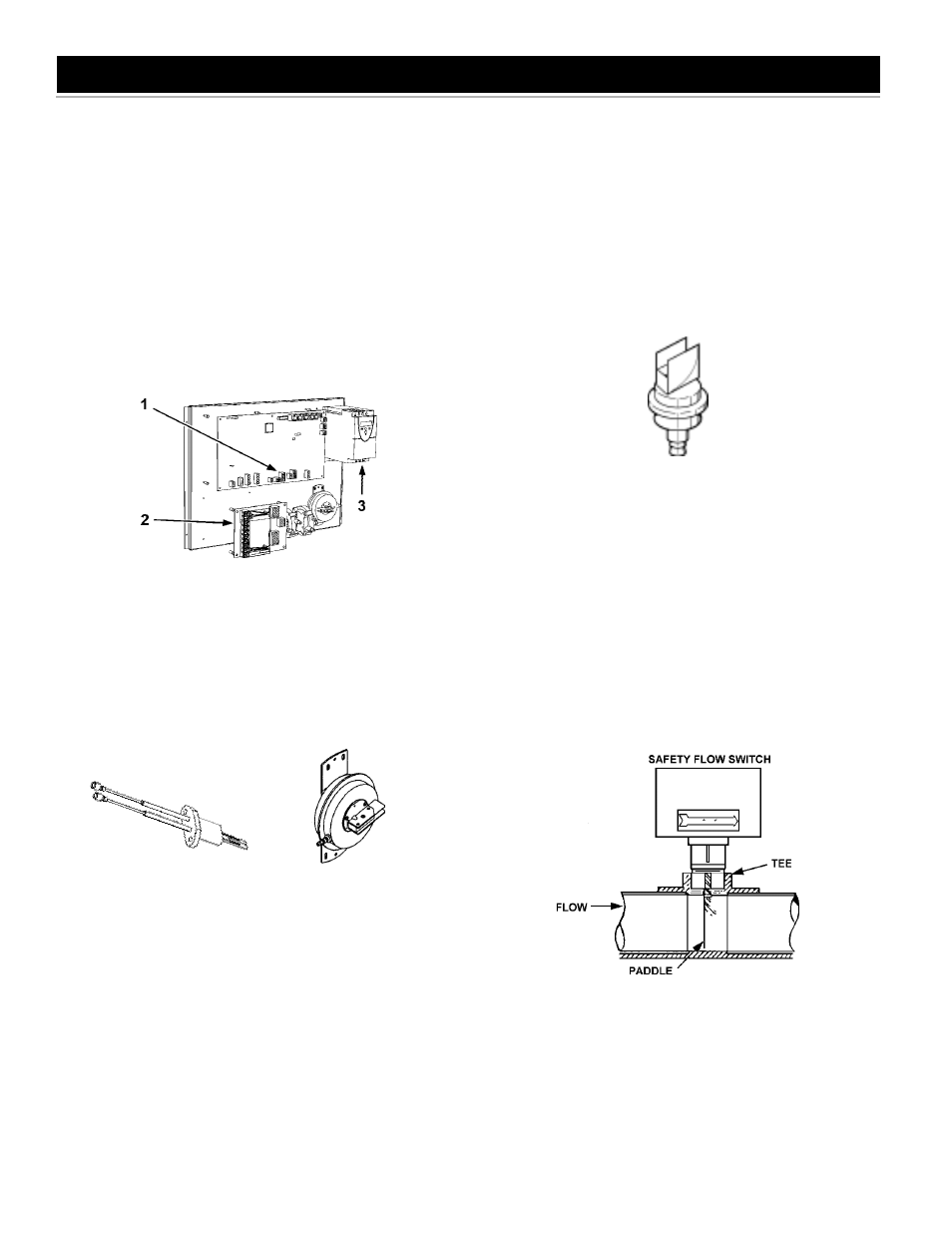
THE CONTROL SYSTEM
The control system consists of four basic components:
1) Modulation Control Board (MCB); 2) Power Distribution Board
(PDB); 3) Variable Frequency Drive (VFD), see Figure 2; 4)
User Interface Module, see Figure 19. The Modulation Control
Board and the Power Distribution Board are located in the control
box and can be accessed by opening the front door of the
unit. The User Interface Module is attached to the front door
panel. Every system will have one Modulation Control Board
(MCB), one Power Distribution Board (PDB), and one User Interface
Module (UIM).
The MCB contains dipswitches which are used to configure
the boiler for several different control options,
see the Control
System Section.
FIGURE 2.
HOT SURFACE IGNITER
The Hot Surface Igniter is a device that ignites the main burner by high
temperature (>1800°F) [982°C], see Figure 3. The igniter is made of
recrystallized silicon carbide, and when 120 VAC is applied to the igniter,
sufficient heat is generated to ignite the main burner. Although
improvements have been made to strengthen the igniter, it is still fragile
and care must be taken in handling the igniter to prevent breakage.
FIGURE 3.
FIGURE 4.
BLOCKED EXHAUST SWITCH
The Blocked Exhaust Switch, see Figure 4, ensures that the vent
system is clear. This exhaust switch is normally closed and only
opens on fault conditions.
BLOWER PROVER SWITCH
This VF boiler has two blower prover switches (BPS). The low
blower prover switch is a single-pole, normally open pressure switch
that closes on increased negative pressure. The low BPS closes
when the blower starts and remains closed during the operation of
the heating cycle.
The second BPS is the high BPS. It is also a single-pole, normally
open pressure switch that closes on increased negative pressure.
The high BPS closes only when the blower is in pre and post purge.
If the high BPS closes at any time during the heating cycle, the
boiler will shut off.
OPTIONAL LOW/HIGH GAS SWITCH
This VF boiler is available with optional low and high gas pressure
switches which meet the CSD-1 code requirements, see Figure 5.
The low gas switch is normally closed and remains closed unless
pressure falls below the preset pressure. The high gas switch is
normally closed and remains closed unless pressure exceeds the
preset pressure.
FIGURE 5. LOW/HIGH GAS PRESSURE SWITCH.
WATER FLOW SWITCH
The water flow switch is installed at the boiler outlet to
prevent burner operation in the event of inadequate water
flow through the boiler. It is a normally open switch that will
close its contacts when increasing water flow rate is detected.
The water flow switch is factory-set. The contacts will open
when the flow rate drops below the factory setting causing
the gas valve to close which will turn off the gas to the
burner, see Figure 6. Under no circumstances shall the
flow switch be tampered with or bypassed. Doing so may
cause damage to the heat exchanger not covered under
the warranty.
FIGURE 6. WATER FLOW SWITCH.
FLAME SENSOR
Each Boiler is equipped with two flame senors coupled together
to detect the presence of the burner flames at high and low
fire conditions. These flame rods work together as one to
sense the flame.
If no flame is sensed, the gas valve(s) will close
automatically. If no flame is sensed on three ignition trials, the boiler
will lock out. In the event of a lockout, depress the SELECT button
on the display board to restart the boiler.
FEATURES