Torque adjustment, Friction disc replacement, Magnet assembly replacement – Dings Dynamics Group 60 Series Coupler NEMA 4X User Manual
Page 5
Torque Adjustment
Caution: Load to be removed or blocked. Brake may be
inoperative during this procedure.
The magnetic disc brake is factory set for rated static torque.
The brake can be adjusted to reduce torque which increases
stopping time. Do not attempt to adjust brake for higher
torque, as this will cause premature coil burnout.
Refer to Figure 3.
1.
To adjust, remove access window cap assemblies (9) to
expose torque locknuts (25U) which are above torque
springs (25G).
2.
To increase stopping time and reduce torque, turn both
torque locknuts (25U) counterclockwise, increasing
spring length. Each full turn reduces torque 7% to 10%
depending on the model.
Friction Disc Replacement
Caution: Load to be removed or blocked. Brake will be
inoperative during this procedure.
If brake model number has a prefix VO, or VU, see page 8.
When total wear on a rotating friction disc (10) reaches
1/16”, replace disc:
Refer to Figs. 3 and 10.
Removing operator assembly
1.
Disconnect power.
2.
Remove any equipment mounted on the brake C face,
such as a gear reducer, by removing nuts (30) and lock-
washers (29). If no equipment is mounted on brake C
face, remove nuts (30) and lockwashers (29).
3.
For two-piece shaft design: Remove adapter housing (7)
which includes shaft (8).
For one-piece shaft design: Remove entire brake from
motor C face. Remove retaining ring (13) or (37) from
brake shaft (8A). Press shaft (8A) out of ball bearing (12)
or (35) in adapter housing (7). A wheel puller using
openings on side of adapter housing (7) may be used.
4.
Remove operator assembly (25) by removing screws (11)
and pivot stud (19). Item 19 has a hex socket in end of
stud for removal.
NOTE: Do not loosen nuts (6) on pivot stud (19), or
“Pivot Stud Adjustment” on page 6 to quiet the magnet
will have to be made again.
5.
Replacing the friction disc
For two-piece shaft design:
Remove worn rotating discs (10) and stationary discs (2).
Replace worn discs and install new discs in the same
order. Install stabilizer clip (23), if furnished, on rotating
discs prior to installing.
For one-piece shaft design:
Remove worn rotating discs (10) and stationary discs (2).
Lay bracket (1) on a flat surface. Place a 5/16” thick
spacer (1”x1”, or 2”x2”) on flat surface in the center of
the brake.
Place shaft (8A) in center of bracket with splined end
down. Replace worn discs in the same order. Install sta-
bilizer clip (23), if furnished, on rotating discs prior to
installing.
6.
Re-assembly of operator assembly (25)
Turn two screws (25M) counterclockwise five turns.
Place operator assembly onto brake bracket (1) and
install two screws (11). Replace compression spring (3),
bushing (5), washer (6), and pivot stud (19) which has
the two nuts (6) in place. Tighten firmly.
7.
Readjust magnet air gap “A” as described under “Wear
Adjustment” on page 4.
8.
Check manual release operation before completing
installation. Adjust per “Manual Release Adjustment” on
page 7 if required.
9.
Completing installation
For two-piece shaft assembly: Reassemble as described
under “Installation” (for models with two-piece shaft
design).
For one-piece shaft assembly: Place adapter housing (7)
over shaft (8A). Press bearing in adapter housing onto
shaft by applying pressure to the inner race of the bearing
only. NOTE: The 5/16” thick spacer as described in Step
5 must still be in place. Replace retaining ring (13) or
(37). Remove four threaded rods (28) or (32) from the
motor and complete assembly as described under
“Installation” (for models with one-piece shaft design).
Magnet Assembly Replacement
Caution: Load to be removed or blocked. Brake will be
inoperative during this procedure.
Refer to Figs. 3, 5 and 10.
1.
Disconnect power supply.
2.
Remove adapter assembly as described under “Friction
Disc Replacement” at left.
3.
Remove two capscrews (25D), wire clamps (25E),
magnet assembly (25A) and shock mount (25C).
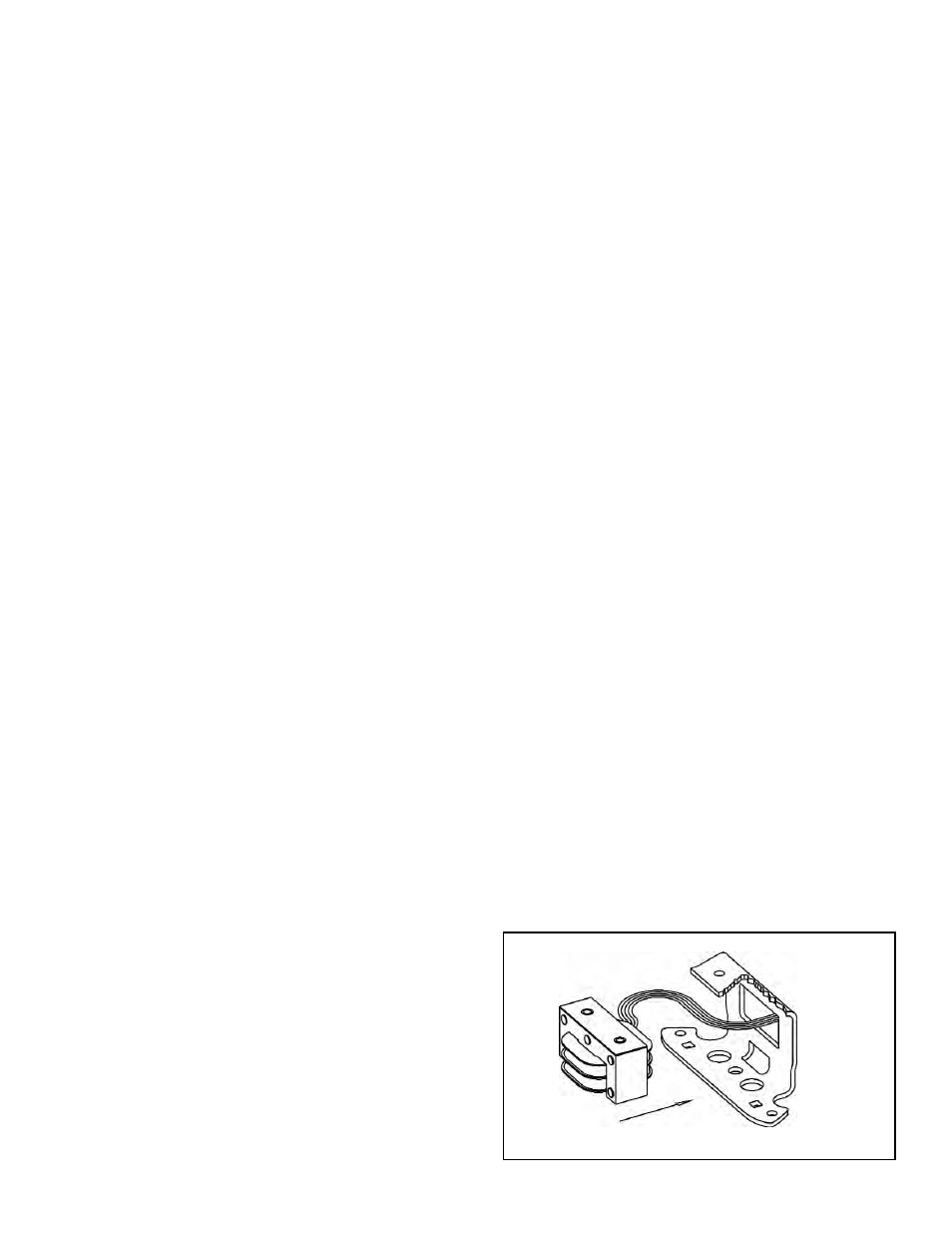
4.
Replace shock mount and magnet, feeding coil wires
through hole in back of bracket (25B) as shown in Fig. 5.
Tighten mounting screws with 55 to 60 lb. in. torque.
5.
Set air gap “A” as described under “Wear Adjustment”
on page 4.
6.
Energize coil. Magnet should be quiet; if not, refer to
“Pivot Stud Adjustment” on page 6.
7.
Check manual release. If it does not operate properly,
adjust as outlined under “Manual Release Adjustment”
on page 6.
8.
Reassemble as described under “Friction Disc
Replacement” and “Installation” on page 2.
Figure 5
5