Dings Dynamics Group 40 Series small frame User Manual
Page 3
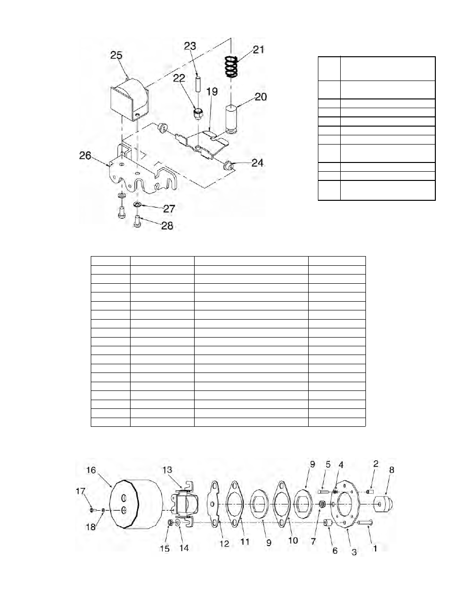
ITEM
NO.
DESCRIPTION
19
Lever Assembly includes
Clinch Nut (22)
20
Solenoid Plunger
21
Torque Spring
22
Clinch Nut #10-32
23
Set Screw #10-32x3/4
24
Nylon Bushing
25
Solenoid includes Plunger
(20) (115V 60Hz)
26
Mounting Bracket
27
Lock Washer #10
28
Screw Fillister HD
#10-32 x .375
Table 2. Parts for Operator
Assembly*
*Operator Assembly sold as complete unit only.
See Table 3, Item 13.
Table 3. Replacement Parts for Brake Assembly
*Specify model number and bore size.
**Specify model number, voltage and hertz.
Figure 4. Operator Assembly
Components
Figure 5. Brake Assembly Components
ITEM NO.
PIECES REQ’D
DESCRIPTION
PART NO.
1
2
Round head screw
W001002-105
2
4
Spacer
G040032-001
3
1
Bracket
G040029-001
4
4
Lockwasher
W004006-003
5
4
Fillister hd screw
W001009-026
6
2
Spacer
G040040-001
7
1
Grommet
W027001-002
8
1
Hub w/ set screws
*
9
2
Rotating disc
G040041-001
10
1
Stationary disc-inner
G040044-001
11
1
Stationary disc-outer
G040042-001
12
1
Pressure plate
H040024-001
13
1
Operator assembly
**
14
2
Washer
W004003-002
15
2
Locknut
W003001-013
16
1
Cover
H040025-001
17
2
Screw, slotted hex washer head
W001046-042
18
2
Lockwasher
W004006-003