9 the usb-mea256 device – Multichannel Systems USB-MEA256-System Manual User Manual
Page 25
USB-MEA256-System
19
4.9 The
USB-MEA256
Device
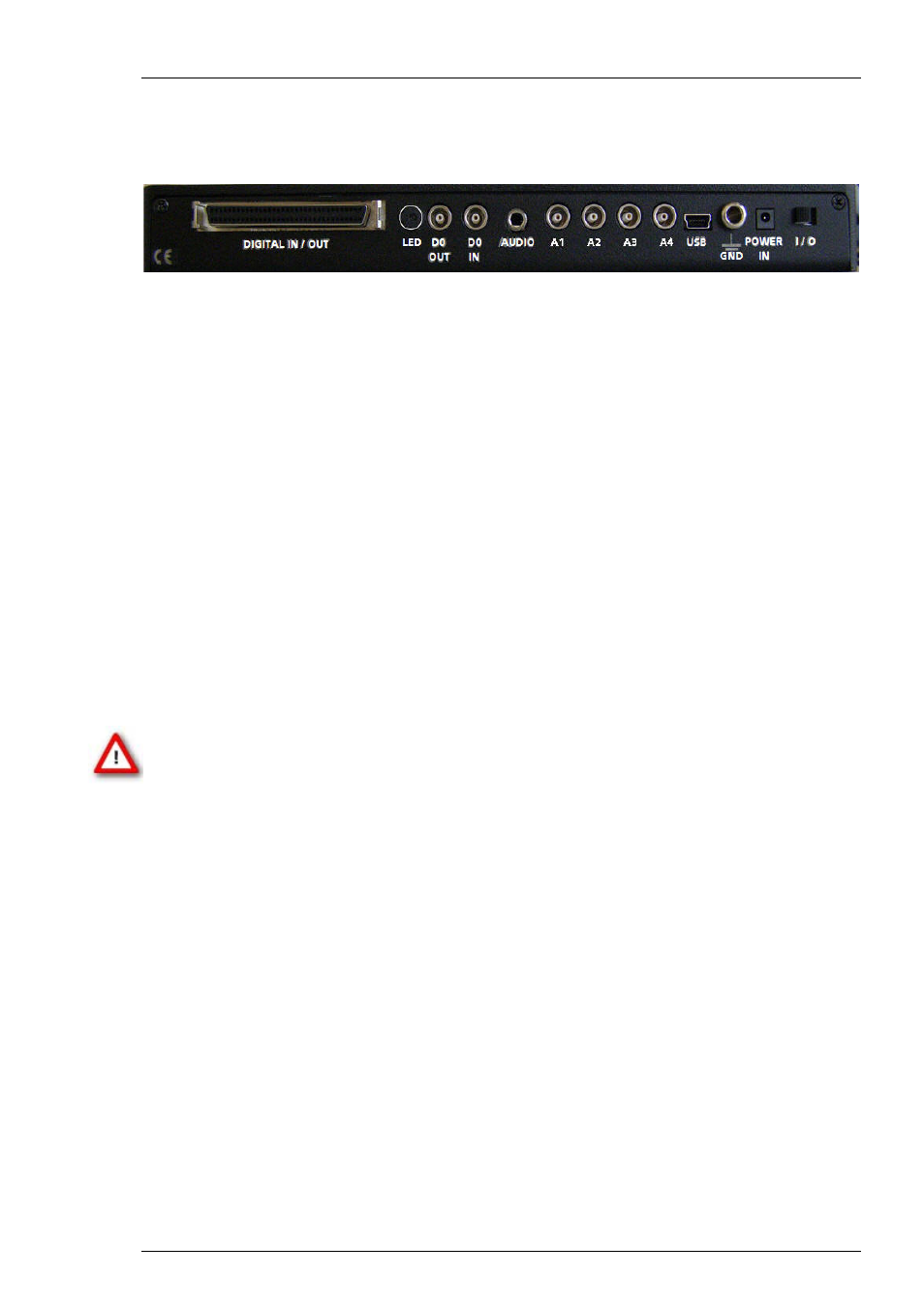
4.9.1 Rear
Panel
DIGITAL IN / OUT
A Digital IN / OUT for 16 digital in- and output bits is available (68-pin MCS standard connector).
The Digital IN / OUT connection accepts or generates standard TTL signals. TTL stands for
Transistor-Transistor Logic. A TTL pulse is defined as a digital signal for communication between
two devices. A voltage between 0 V and 0.8 V is considered as a logical state of 0 (LOW), and
a voltage between 2 V and 5 V means 1 (HIGH).
The Digital OUT allows generating a digital signal with up to 16 bits and read it out, for example,
by using a Digital IN / OUT Extension Di/o from Multi Channel Systems MCS GmbH. You can
utilize this digital signal to control and synchronize other devices with the USB-MEA256-System.
Bit 0 of the Digital OUT is separated and available as Lemo connector DIG OUT D0. So if you need
only one bit of the digital signal, you don’t need the additional signal divider SD16. Please read
chapter "Pin Layout" (Digital IN / OUT Connector) in the Appendix for more information.
The Digital IN can be used to record additional information from external devices as a 16-bit
encoded number. The Digital IN is most often used to trigger recordings with a TTL signal from
a stimulator.
The 16 bit digital input channels is a stream of 16-bit values. The state of each bit (0 to 15) can
be controlled separately, the state can be HIGH (1) or LOW (0). Standard TTL signals are accepted
as input signals on the digital inputs. Unused input bits, which have an undefined state, should
be masked in the Trigger Detector of MC_Rack.
Warning: A voltage that is higher than +5 Volts or lower than 0 Volts, that is, a negative
voltage, applied to the digital input would destroy the electronics. Make sure that you apply
only TTL pulses (0 – 5 V) to the digital inputs.
Power LED
The Power LED lights up when the USB-MEA256 is connected via power supply unit
to the power supply system, and the toggle switch on the rear panel is switched on.
Digital Output D0 OUT
The Bit 0 of the Digital OUT is also accessible independently from the 68-pin Digital IN / OUT
connector with a Lemo connector. The digital output channel D0 is generally used for
synchronizing the USB-MEA256-System with a stimulus generator, or with another data
acquisition system, for example, an imaging or a patch clamp system. The D0 OUT generates
standard TTL pulses.
Digital Input D0 IN
The Bit 0 of the Digital IN is also accessible independently from the 68-pin Digital IN / OUT
connector with a Lemo connector. The digital output channel D0 is generally used for
synchronizing the USB-MEA256-System with a stimulus generator, or with another data
acquisition system, for example, an imaging or a patch clamp system. The D0 IN accepts standard
TTL pulses.