Multichannel Systems USB-MEA256-System Manual User Manual
Page 23
USB-MEA256-System
17
Using 256MEA Electrodes for Stimulation
The electrodes of the 256MEAs can also be used for electrical stimulation. Around the open area
for the 256MEA, there are two rows of connection sockets on each side in the lid of the amplifier.
There is one socket for each electrode and four ground sockets. These sockets can be used to
connect each electrode to a stimulus generator, for example, a STG4000 from Multi Channel
Systems MCS GmbH. The ground sockets can be used to connect other devices, like the stimulator,
or the perfusion to the systems ground. You will find the layout map of the sockets in chapter
"Pin Layout" in the Appendix.
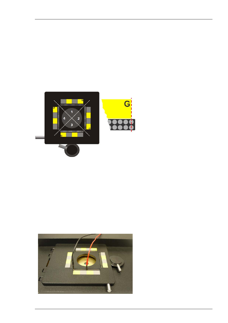
To make it easier to find the correct socket for each electrode, stickers are included to color code
the electrode sockets in four blocks of 2 x 8 sockets, corresponding to the color code used in the
layout map in chapter "Pin Layout" in the Appendix. If you want to do electrical stimulation,
please attach the stickers as shown in the image below. The edge of the sticker has to be aligned
with the first pair of sockets.
The position of the four ground sockets is labeled with a G. The connection sockets are arranged
in quadrants. The electrodes in quadrant 1 have their sockets in the upper row, electrodes in
quadrant 2 in the right row and so on.
To find the connection socket for a specific electrode, please do following:
Determine the quadrant the electrode is in.
Look up the exact position of the socket in the layout map .
Determine the label (yellow/grey) the socket belongs to.
Count the sockets from the edge of the label.
Plug in the stimulation adapter ADPT-STIM-MEA256 in the correct connector socket.
Connect the ADPT-STIM-MEA256 via laboratory cable with the stimulus generator STG.