Hhy yf fiir re e 6 6a al l2 2, Hh yy ff iirr ee 66 aa ll 22, Installing the hyfire – Mallory Ignition Mallory HYFIRE 6AL2 ELECTRONIC IGNITION CONTROL 6861m User Manual
Page 8: 6al2 with a dual connector coil hei system
www.malloryracing.com
8
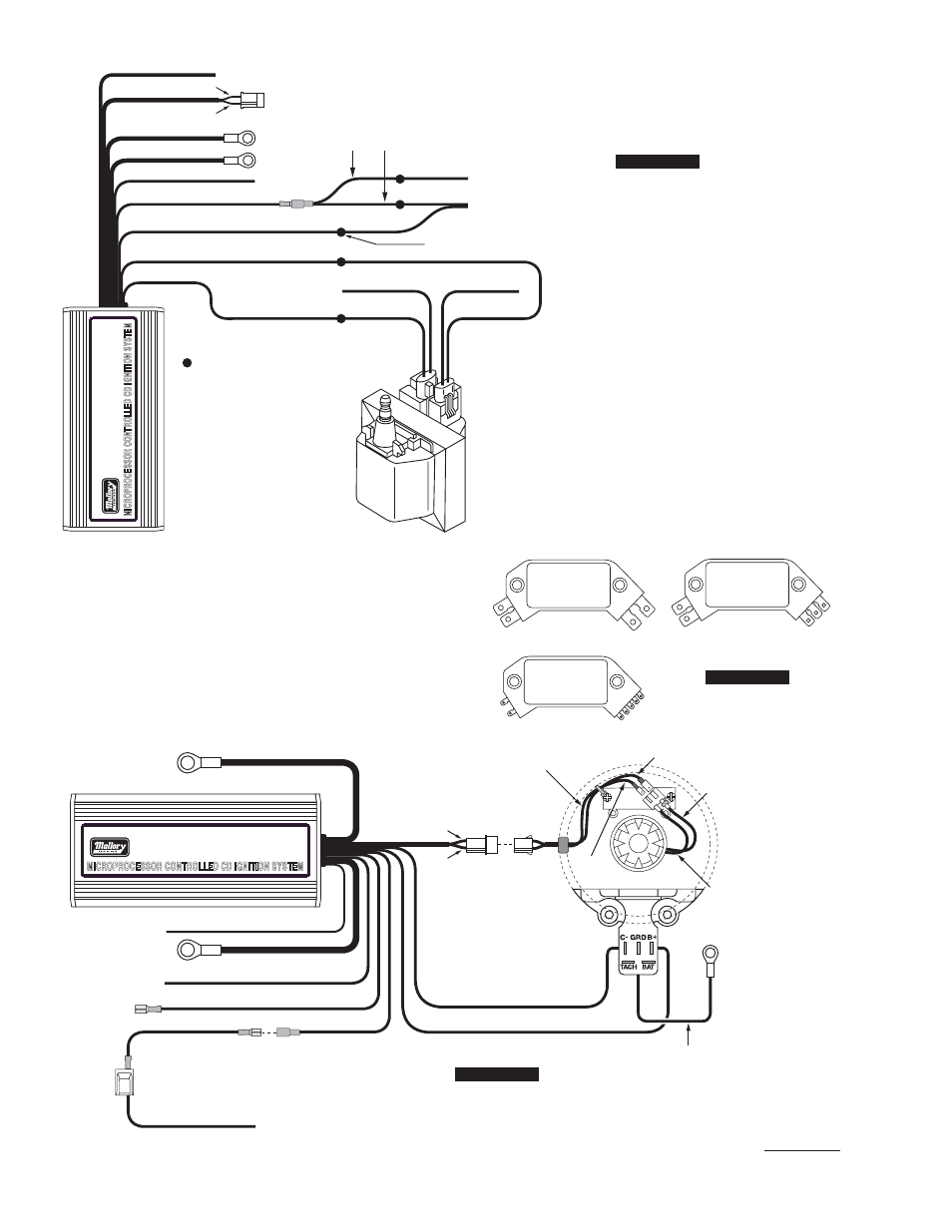
There are three different large cap HEI distributors. To identify which
of the following diagrams fit your specific application, remove the
distributor cap and rotor and locate the ignition module at the base
of the distributor. Count the number of terminals on both ends of the
module and follow the corresponding diagram. GM used 4, 5, and
7-pin modules in these distributors.
NOTE: Some 5-pin modules may experience a hesitation or stall on
deceleration. If this occurs, contact the Mallory Technical Service
Department for the required bolt-in diode to correct the problem.
4-Pin Module
5-Pin Module
®
PART No. 6861M
WHITE
BLUE
RED (SMALL 18 GA)
NOT USED
YELLOW
TO TACHOMETER
AUX RPM LIMITER
BLACK (LARGE 14 GA)
TO BATTERY NEG (-)
RED (LARGE 14 GA)
TO BATTERY POS (+)
BLACK (SMALL 18 GA TO Cñ)
ORANGE (TO B+)
PURPLE
GREEN
WHITE
GREEN
TO ENGINE
GROUND
WHITE JUMPER
KEY CONNECTOR
HEAVY RED OR PINK WIRE FROM CAR
WIRING HARNESS
GREEN
PURPLE
PART OF MALLORY HEI KIT
P/N 29008 (NOT INCLUDED)
PART OF MALLORY HEI KIT
P/N 29008 (NOT INCLUDED)
Installing the HYFIRE
®
6AL2 with an HEI
4-Pin Module (Magnetic Pickup Trigger)
7-Pin Module
FIGURE 14
FIGURE 15
®
PART OF MALLORY HEI
KIT P/N 29008 (NOT
INCLUDED)
YELLOW
WHITE
WHITE
BLACK
WHITE
WHITE (NOT USED)
SPLICE WIRES AT THESE LOCATIONS
PINK (NOT USED)
CONNECT FACTORY TACH HERE
FROM DISTRIBUTOR
TO IGNITION SWITCH
WHITE
GREEN
PURPLE
BLUE
RED (SMALL 18 GA)
BLACK (LARGE 14 GA)
RED (LARGE 14 GA)
RED
RED
PINK
PINK
ORANGE
PINK
TO BATTERY NEG (-)
TO BATTERY POS (+)
AUX RPM LIMITER
TO TACHOMETER
Installing the HYFIRE
®
6AL2 with a
Dual Connector Coil HEI System
HH
YY
FF
IIRR
EE
66
AA
LL
22
FIGURE 13
H
HY
YF
FIIR
RE
E 6
6A
AL
L2
2