Settings & diagnostics, Input signal sensitivity adjustment (r1), Diagnostic operational leds (d1 & d2) – Liquid Controls SP714-S2i User Manual
Page 11: Diagnostic test oscillator (sw2), Maintenance - cpu board replacement, Do not use the sw2 during operation
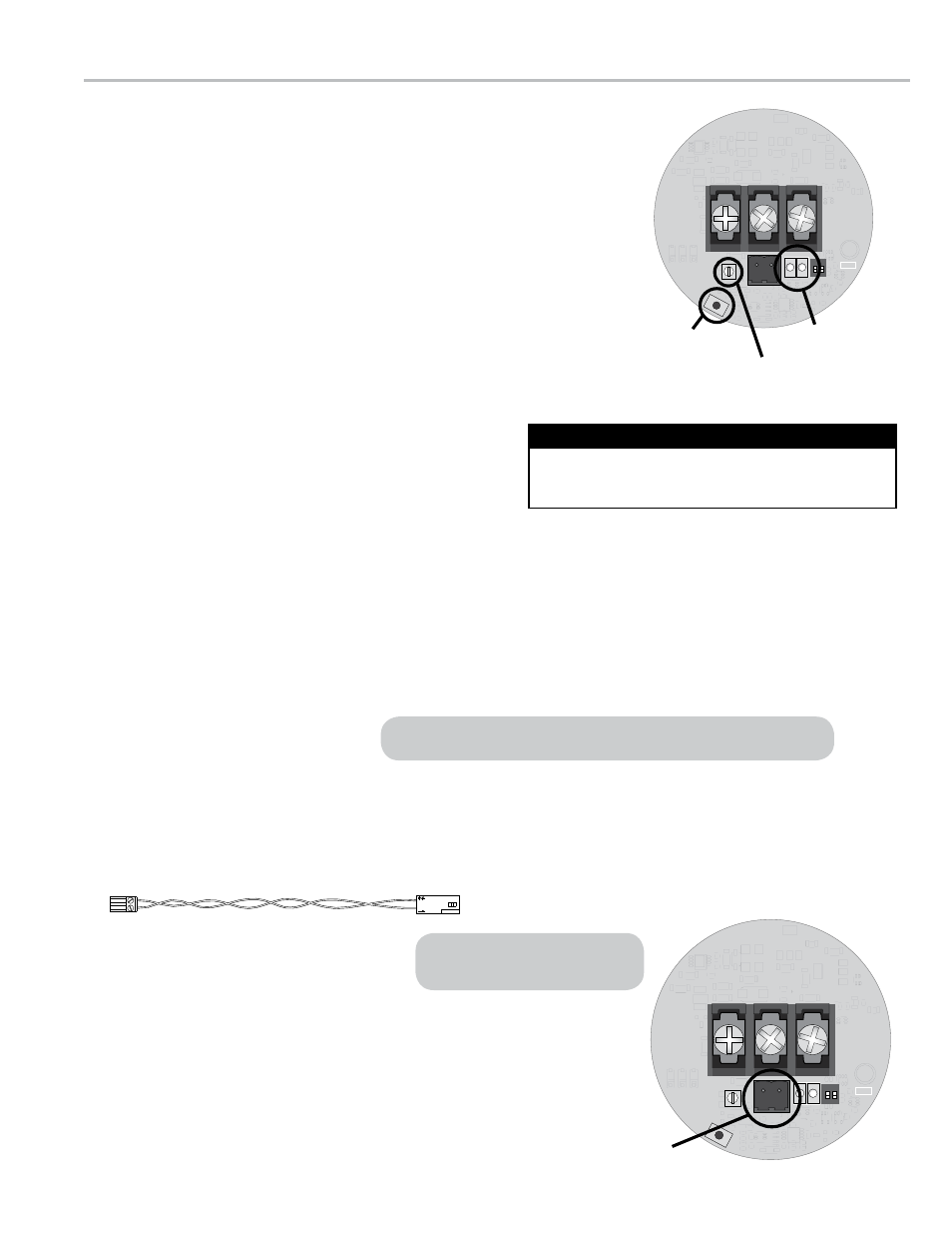
Input Signal Sensitivity Adjustment (r1)
The R1 Input Signal Sensitivity Adjustment is a valuable tool that, in addition
to SP714-S2i being directly mounted to the turbine meter, allows effective
operation in noisy environments. The R1 is a potentiometer that sets the
amplitude of the input signal (from the pickup coil) that the SP714-S2i will
accept as a valid pulse.
Adjusting R1 allows the SP714-S2i to differentiate between the input signal
and any noise in the system. Turning the R1 clockwise decreases the
amplitude of the input signal required for a valid pulse, and turning the R1
counterclockwise increases the required amplitude.
The detection level of the R1 potentiometer is set at approximately 17 mV
rms at the factory. A red varnish is applied to the potentiometer screw to seal
the factory setting.
settInGs & dIaGnostIcs
SW1
S1
J U 4
D1
D2
GND
TB2
S2
R1
TB1
ON
ON
1 2
GND
1
R1
Input Sensitivity
Adjustment
sW2
Diagnostic Test
Oscillator
D1 & D2
Diagnostic LEDs
Diagnostic Operational LeDs (D1 & D2)
There are two Diagnostic Operational LEDs (D1 and D2) on the SP714-S2i PC board that indicate the current
operational status of the preamplifier. The green LED (D1) indicates the power supply status. When the green LED is
on, the power supply is sufficient. When the LED is dim or flashing, the preamplifier does not have sufficient power.
The red LED (D2) indicates the status of the signal traveling through the preamplifier. The red LED flashes at the
same rate as the frequency as the signal passing through the SP714-S2i. If the LED is not flashing, no signal is
passing through the amplifier. If the signal frequency is above 40 Hz, the light will flash very quickly and the LED will
appear to be constantly illuminated. If the input into the SP714-S2i stops on a positive portion of the signal pulse, the
LED will be illuminated constantly.
Diagnostic Test Oscillator (SW2)
The SW2 Diagnostic Test Oscillator verifies that the SP714-
S2i is operational. To activate the test, press the SW2 push
button. A 10 Hz signal will be introduced into the SP714-
S2i signal output pins (TB1). For best results, use the SW2
Diagnostic Test Oscillator without the presence of the pickup
coil signal.
If an input signal from the pickup coil is present, the 10 Hz
signal from the SW2 can disrupt the SP714-S2i output signal
and an error will be detected by the pulse acquisition device.
Do Not Use the SW2 During Operation
The D1 and D2 LEDs are inoperable in the 2-wire Standard configuration.
Polarity of the connector at the
pickup coil is not important.
maintenance - cPu board replacement
The CPU board (PN 85025) is the only SP714-S2i part available for purchase. If you are replacing the 85025 CPU
board, the wiring harness, which connects the pickup coil and to the SP714-S2i CPU board, must be unplugged from
the old CPU board and plugged into the replacement board, then wired appropriately.
To replace the 85025 CPu board:
1. Remove the SP714-S2i housing cover.
2. Pull the CPU board from the housing, disconnect the
wires to the power supply and the pulse acquisition
device, and unplug the wiring harness.
3. Plug the wiring harness into the replacement CPU board,
wire the replacement CPU board to the power supply
and the pulse acquisition device, set the board into the
housing, and replace the housing cover. See pages 7-10 for
detailed instructions.
Wiring Harness
SW1
S1
J U 4
D1
D2
GND
TB2
S2
R1
TB1
ON
ON
1 2
GND
1
Input signal
connector
11