Laurel Electronics LAUREATE SERIES SCALE-WEIGHT METER User Manual
Page 14
14
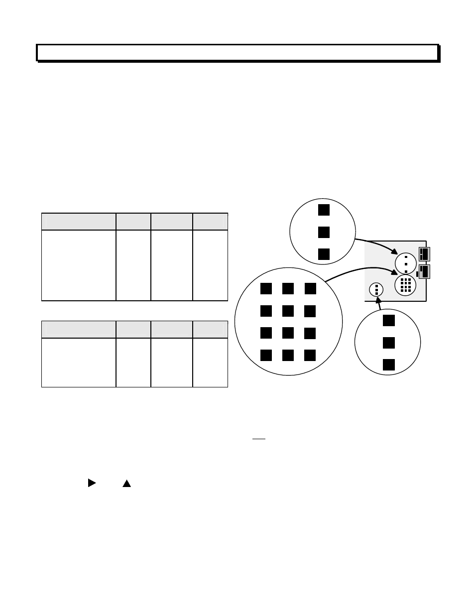
11. PROCESS & STRAIN INPUT JUMPERS
Process and strain input scale meters utilize the DC signal conditioner board, which offers
sensitivity to ±200 mV and can operate in a ratiometric mode, which removes effects caused
by variations in the excitation supply. This board needs to be configured via jumpers for the
desired voltage or current range. All signal ranges are factory calibrated with calibration factors
stored in EEPROM. The meter software recognizes the board and will bring up the appropriate
menu items for it; however, it does not recognize the jumper settings. Please see further
manual sections for relay output, analog output, communications, and transducer excitation
output.
RANGE SELECTION VIA JUMPERS
1. Letters indicate jumper position. Jumpers are installed on pins adjacent to letters.
2. Use 5 mm (0.2") jumpers for locations designated by a capital letter.
3. Use 2.5 mm (0.1") jumpers for locations designated by a lower case letter.
4. Store spare jumpers on an unused jumper post not associated with a capital letter.
SCALE & OFFSET SETUP
For process, strain, and load cell scale meters, scaling is normally set up from the front panel
using the
and
keys, but can also be set up via RS232/485 using PC-compatible
Instrument Setup software (available at no charge). The meter allows three scaling methods to
be selected: 1) Scale & Offset method, 2) Coordinates of 2 Points method, or 3) Reading
Coordinates of 2 Points method. Only menu items applicable to the selected method will be
presented. Please see the Glossary for an explanation of each method.
Voltage Ranges Jumpers
FS Input
E1
E2
E3
±200.00 mV
±2.0000 V
±20.000 V
±200.00 V
±300V (UL)
±600V (not UL)
A
A
B
B
B
B
f
f
h
h
g
g
b
a
b
a
a
a
Current Ranges Jumpers
FS Input
E1
E2
E3
±2.0000 mA
±20.000 mA
±200.00 mA
±5.000 A
A
A
A
A
e, g
d, g
c, g
a, b, g
b
b
b
b
E1
a
E2
b
E3
h
a
g
e
d
c
b
f
B
A