Technical description, Internal baud rate generator, Control and status registers definition – Impulse 5402 User Manual
Page 7
© Sealevel Systems, Inc.
- 5 -
ACB-MB+4.PCI User Manual
Technical Description
The ACB-MB+4.PCI utilizes the Zilog 85230 Enhanced Serial Communications
Controller (ESCC) and includes a dedicated Z85230 per port. This chip features
programmable baud rate, data format and interrupt control. Refer to the ESCC Users
Manual, available from Zilog, for details on programming the 85230 ESCC chip.
Internal Baud Rate Generator
The baud rate of the ESCC is programmed under software control. The standard
oscillator supplied with the board is 7.3728 MHz. However, other oscillator values
can be substituted to achieve different baud rates.
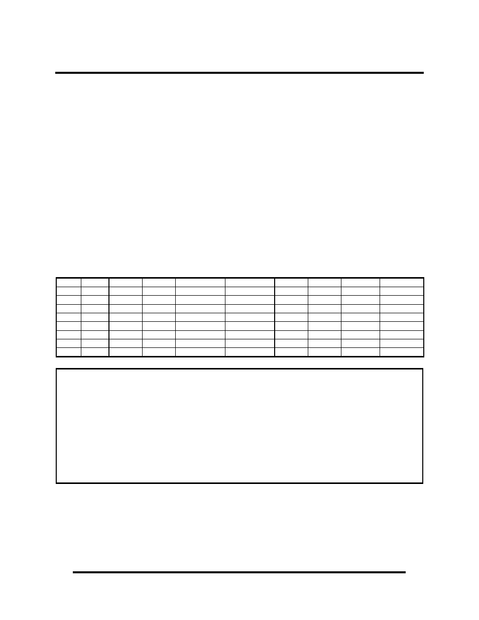
Control and Status Registers Definition
The control and status registers occupy 12 consecutive I/O locations. The following
tables provide a functional description of the bit positions. X = do not care.
Base
Mode
D7 D6
D5
D4
D3 D2 D1
D0
+4
RD 0 IRQST 0
0
0 0
0
DSRA
+5
RD 485CLK
ECHOA
SYNCA_RTS
SYNCA_CTS AM3 AM2
AM1
AM0
+5
WR 485CLK
ECHOA
SYNCA_RTS SYNCA_CTS AM3 AM2
AM1
AM0
+6
RD 0 0
0
0
RLA
LLA
TSETSLA
RXCOPTA
+6
WR X X
X
X
RLA LLA
TSETSLA
RXCOPTA
+7
RD X X
X
X IRQST4
IRQST3
IRQST2
IRQST1
+14
RD SD7 SD6
SD5
SD4
SD3 SD2 SD1
SD0
+15
RD SD15 SD14
SD13
SD12
SD11 SD10 SD9
SD8
Field Description
IRQST
SCC interrupt status:
1 = No interrupt pending on ESCC
0 = Interrupt pending on ESCC.
DSRA
DSRA:
1 = DSRA not active
0 = DSRA active
LLA
Local Loopback:
1 = LL set
0 = LL not set
RLA
Remote Loopback:
1 = RL set
0 = RL not set
TSETSLA
TSET clock source:
1= Received TXC as source
0 = TRXCA as source
RXCOPTA
RXCOPTA:
1= Selects SCC PCLK for RTXCA
0 = Selects received RXC for
RTXCA
SYNCA_RTS
SYNCA _RTS:
1 = SYNCA connected to RTS
0 = SYNCA is high
SYNCA_CTS
SYNCA_CTS:
1 = SYNCA connected to CTS
0 = SYNCA is high
485CLK
TSET switches with TXD:
1 = clk switches
0 = no CLK switching
ECHOA
ECHO enable:
1 = echo disabled
0 = echo enabled
AM0 – AM3
I/O mode select. See table for valid interface options.
0 = High Impedance
SD0 – SD15
Optional security feature. Unique value per customer or application.
Default value = FFFF
Note: Default values are listed in bold