Impulse 5402 User Manual
Page 11
© Sealevel Systems, Inc.
- 9 -
ACB-MB+4.PCI User Manual
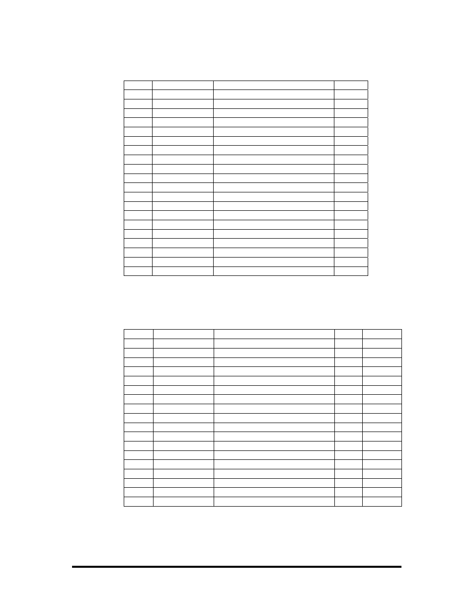
RS-530A
Base+5, M3-M0=F, 1111
Pin #
Signal
Name
Mode
2
TDA TX–
Transmit Negative
Output
3
RDA RX–
Receive Negative
Input
4
RTSA RTS–
Request To Send Negative
Output
5
CTSA CTS–
Clear To Send Negative
Input
6
DSRA DSR–
Data Set Ready Negative
Input
7 GND
Ground
8
DCDA DCD–
Data Carrier Detect Negative
Input
9
RXCB RXC+
Receive Clock Positive
Input
11
TSETB TSET+
Transmit Signal Element Timing +
Output
12
TXCB TXC+
Transmit Clock Positive
Input
13
CTSB CTS+
Clear To Send Positive
Input
14
TDB TX+
Transmit Positive
Output
15
TXCA TXC–
Transmit Clock Negative
Input
16
RDB RX+
Receive Positive
Input
17
RXCA RXC–
Receive Clock Negative
Input
18 LL
Local
Loopback
Output
19
RTSB RTS+
Request To Send Positive
Output
20
DTRA DTR–
Data Terminal Ready Negative
Output
21 RL
Remote
Loopback
Output
24
TSETA TSET–
Transmit Signal Element Timing –
Output
V.35 Signals
Base+5, M3-M0=E, 1110
Pin #
Signal
Name
V.35
Mode
2
TDA TX–
Transmit Negative
P
Output
3
RDA RX–
Receive Negative
R
Input
4
RTS
Request To Send
C
Output *
5
CTS
Clear To Send
D
Input *
6
DSR
Data Set Ready
E
Input *
7 GND
Ground
B
8
DCD
Data Carrier Detect
F
Input *
9
RXCB RXC+
Receive Clock Positive
X
Input
11
TSETB TSET+
Transmit Signal Element Timing +
W
Output
12
TXCB TXC+
Transmit Clock Positive
AA
Input
14
TDB TX+
Transmit Positive
S
Output
15
TXCA TXC–
Transmit Clock Negative
Y
Input
16
RDB RX+
Receive Positive
T
Input
17
RXCA RXC–
Receive Clock Negative
V
Input
18 LL
Local
Loopback
Output
*
20
DTR
Data Terminal Ready
H
Output *
21 RL
Remote
Loopback
Output
*
24
TSETA TSET–
Transmit Signal Element Timing –
U
Output
Note: All modem control signals are single ended (un-balanced) with RS-232 signal levels.