System backbone, Specifications: backbone, Specifications: accessories – Impulse MAQ20 User Manual
Page 6: Shape for maq, 20 software, Model number, Front thin module side both modules
.60in
15.3mm
1.11in
28.2mm
7-34
VDC
+
_
SHLD
ETH.
USB
RS-485
Model Number
MAQ20-BKPL4
MAQ20-BKPL8
MAQ20-BKPL16
MAQ20-BKPL24
1 COM Module plus 4 I/O Modules
1 COM Module plus 8 I/O Modules
1 COM Module plus 16 I/O Modules
1 COM Module plus 24 I/O Modules
Expansion & Remote Location
Male/Female pluggable terminal blocks
at each end of backbone allow system
expansion and distributed installation
The
System Backbone
resides within the DIN rail used for module
mounting and provides power to and interface between the commu-
nication module and the I/O modules. Standard backbones provide
for one communication module and 4, 8, 16, or 24 I/O modules. The
longest backbone, which accommodates 24 I/O modules, fits in an
industry standard 19” rack. Each backbone utilizes a pluggable con-
nector system on each end such that varying system channel counts
can be configured using the standard backbones. As a result of this
pluggable system, the main part of a system, including the commu-
nication module, can be installed in one location while other sets of
I/O modules installed in remote locations connect to the main system
through a wire harness.
Specifications: Backbone
Once a system is established with a system backbone and a com-
munication module, system configuration is accomplished by applying
power and installing the I/O modules. These are hot swappable and
true ‘plug and run’. When an I/O module is plugged into any backbone
position, the communication module automatically recognizes that it
has been added to the system, registers it in the system configuration
record, and makes it immediately available in the ReDAQ
®
Shape for
MAQ
®
20 host software for use in data acquisition and control. Simi-
larly, when a module is removed from any backbone position, the com-
munication module recognizes that it has been unplugged, removes it
from the system configuration, and disables it in the ReDAQ
®
Shape
for MAQ
®
20 software.
Model Number
MAQ20-XCA01
MAQ20-XCA02
SLX147-01, -02, -05
SLX141-01, -02, -07
SLX141-X01, -X02, -X07
PWR-PS5RB
PWR-PS5RC
PWR-PS5RD
PWR-PS5RE
SCMXRAIL1-XX
Backbone expansion cable, 1m
Backbone expansion cable, 2m
USB Cable, Type A to Type B, 1m, 2m, 5m
Ethernet Cable, 1m, 2m, 7m
Ethernet Crossover Cable, 1m, 2m, 7m
Power Supply, 24VDC, 0.6A, 100-240VAC Input, DIN Mount
Power Supply, 24VDC, 1.3A, 100-240VAC Input, DIN Mount
Power Supply, 24VDC, 2.1A, 100-240VAC Input, DIN Mount
Power Supply, 24VDC, 4.2A, 100-240VAC Input, DIN Mount
DIN EN50022-35x7.5 (slotted steel), length -xx, in meters
Specifications: Accessories
D
C
B
A
B
C
D
1
2
3
4
5
6
7
8
8
7
6
5
4
3
2
1
E
F
E
F
4-Module Assembly
SHEET 1 OF 1
4-Module Assembly
B
UNLESS OTHERWISE SPECIFIED:
SCALE: 2:1 WEIGHT:
REV
DWG. NO.
C
SIZE
TITLE:
NAME
DATE
COMMENTS:
Q.A.
MFG APPR.
ENG APPR.
CHECKED
DRAWN
FINISH
MATERIAL
INTERPRET GEOMETRIC
TOLERANCING PER:
DIMENSIONS ARE IN INCHES
TOLERANCES:
FRACTIONAL
ANGULAR: MACH BEND
TWO PLACE DECIMAL
THREE PLACE DECIMAL
APPLICATION
USED ON
NEXT ASSY
PROPRIETARY AND CONFIDENTIAL
THE INFORMATION CONTAINED IN THIS
DRAWING IS THE SOLE PROPERTY OF
REPRODUCTION IN PART OR AS A WHOLE
WITHOUT THE WRITTEN PERMISSION OF
PROHIBITED.
A
DO NOT SCALE DRAWING
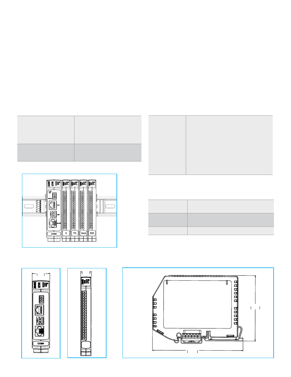
Front Thick Module
Comm Module with 4 I/O Modules on
DIN Rail Mounted Backbone
4.51in
114.6mm
3.26in
82.8mm
Front Thin Module
Side Both Modules
Dimensional Drawings
Specifications: Boost Power Supply Module
Typical at T
A
= +25°C and +24VDC system power
Model Number
MAQ20-PWR3
Power Input
7-34VDC at 2A max
3-position pluggable terminal block
Power Output to Bus
+5VDC at 3A