Controlled Products Systems Group DTEK110VAC User Manual
Page 2
Front Indicators
1. Green Led is ON - the detector is powered.
2. Red Led is ON - the detector detected a vehicle
3. Green Led is Blinking - the loop failed and is shorted or disconnected
4. Green Led is Blinking with two consecutive fast blinks - the loop failed in the past and
now is working correctly.
5. Red Led is Blinking at the start of a vehicle detection - the Filter function is ON
6. Red Led is Blinking at the end of a vehicle detection - the Extend function is ON
7. Red Led is Blinking during a vehicle detection - 4 minute limited presence time has
expired.
Note: Functions on pins 6 and 10 are reversed if DIP 4 is set to OFF
Front Controls
Reset
This toggle switch when pushed momentarily down will reset the detector
Frequency Counter
This toggle switch when pushed momentarily up will count the frequency
on the loop. This count is displayed by the Red Led blinks, each blink
represents frequency of 10K Hz. Count between 3 to 13 blinks confirms
that the loop detector is tuned to the loop.
Frequency
This toggle switch controls the loop frequency. Set different frequencies
on adjacent loops. Verify frequencies with the frequency counter by
counting the Red Led blinks.
Back Controls
Sensitivity
This rotary switch controls the detector sensitivity. During normal
operation the sensitivity level is set to 3 or 4.
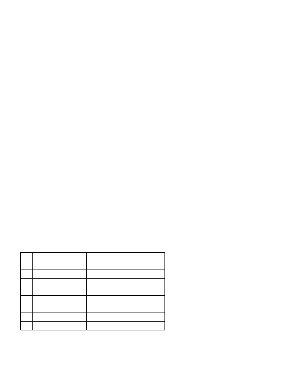
DIP Switch Functions
3 seconds
Extend detect
8
6 seconds
Extend detect
7
Automatic Sensitivity Boost On
ASB Off
6
Filter On
Filter Off
5
"Fail Safe"
"Fail Secure"
4
4 minute limited presence time
Constant presence
3
Pulse on Un-detect
Pulse on detect
2
Presence on Relay II
Pulse on Relay II
1
ON
OFF
DIP
When Dip 7 and 8 are in ON position the extend time is 9 seconds.
DTEK.lwp Created: March 23, 1998 Revised: January 16, 2003 10:44AM Pages:5
Page:2