Product overview, Technical specifications, Controls, indicators and connections – Controlled Products Systems Group NIR User Manual
Page 2: Wiring
NIR Instructions
2
Document no. NIR Instructions.doc
REV 1.2 Date 11/16/2012
Product Overview
Product may be used for activation of gates or doors when the beam is interrupted. The NIR uses an Infrared
signal that is returned from a reflector mounted on the opposite side of the opening to be monitored.
Technical Specifications
Controls, Indicators and Connections
Top
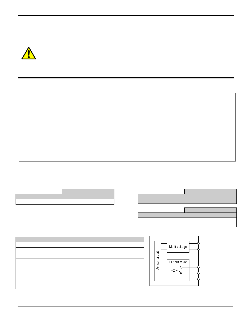
Wiring
Brown (+)
Blue (-)
Black (NC)
Gray (NO)
White (COM)
Shown energized and aligned
Power Supply
12 – 240 VDC 24 – 240 VAC
Power Supply Tolerance
+ / -10%
Current Draw
28mA standby 15mA detected @ 12 VDC
Housing Material
ABS and Acrylate on lenses
Relay Type
SPDT 2A @ 24 VDC 0.6A @ 220VAC
Temperature Range
-20 - +60C
Connector
Cable 2 Meter (6 feet)
Environmental Protection
IP 66 IEC
Size
1.6” x 2.6” x 0.8”
Response time
10ms maximum
Range
0.3 – 30 feet
Certifications
CE
Sensitivity
Clockwise increases sensitivity
Normally set to maximum (single turn)
Yellow LED
LED is on when unit is energized and signal is
stabile
Red LED
Is on when is energized and alignment is correct
LED is off when unit is energized and object is
detected or not aligned
Wire Color Connections
Brown
Power Positive (+)
Blue
Power Negative (-)
Black
Internal Relay Contact Normally Closed (NC)
Gray
Internal Relay Contact Normally Open (NO)
White
Internal Relay Contact Common (COM)
Comments: The Blue wire and Brown wire are not polarity
sensitive. Unit is designed to operate on AC power
WARNING …
Not to be used for Personnel Protection
Never use product as sensing devices for personnel
protection. Doing so could cause serious injury or death.
These sensors do NOT include the self-checking redundant circuitry
necessary to allow their use in personnel safety applications. A sensor failure or
malfunction can cause either an energized or de-energized sensor output
condition. UL 325 Non-compliant