Important – Controlled Products Systems Group E-960-D190Q User Manual
Page 6
6
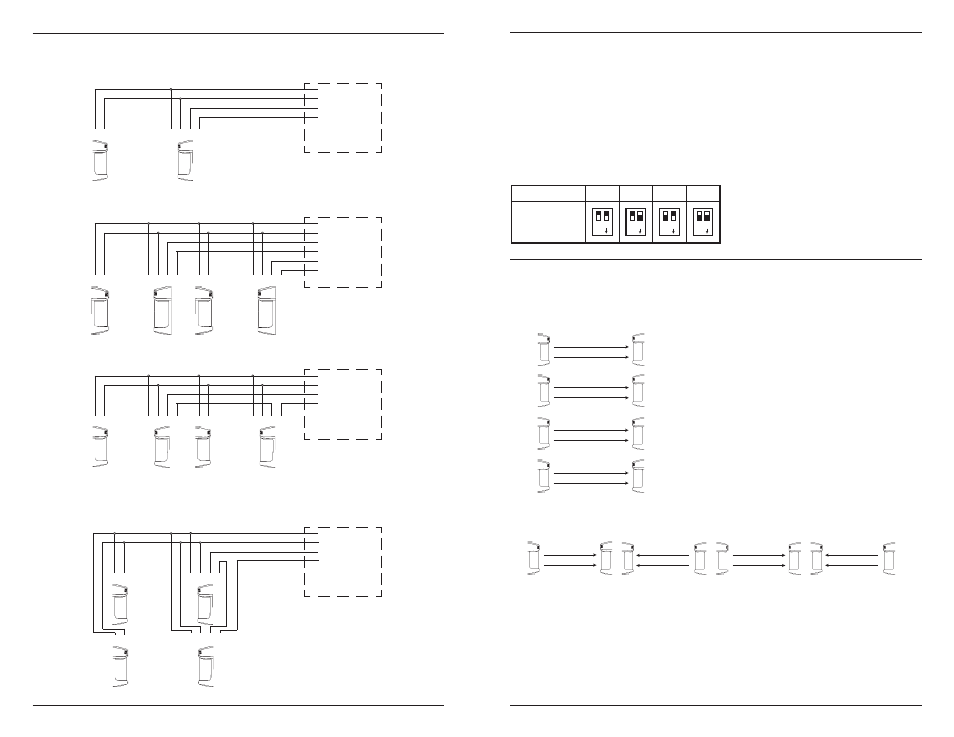
Fig. 9: Examples of Possible Ways To Connect One or More Sensors
➀ ➁
➀ ➁ ➂ ➃
Control panel
(12VDC)
}
Power
}
Alarm signal
Transmitter
Receiver
➀ ➁
➀ ➁ ➂ ➃
Control panel
(12VDC)
}
Power
}
Alarm signal
Transmitter
Receiver
Example connection 3 - In-line Single Channel
➀ ➁
➀ ➁ ➂ ➃
Transmitter
Receiver
➀ ➁
➀ ➁ ➂ ➃
Control panel
(12VDC)
}
Power
}
Alarm (ch. 1)
Transmitter
Receiver
Example connection 2 - Dual Sensors, Separate Channels
➀ ➁
➀ ➁ ➂ ➃
Transmitter
Receiver
}
Alarm (ch. 2)
Example connection 1 - Standard
➀ ➁
➀ ➁ ➂ ➃
}
Power
}
Alarm signal
Example connection 4 - Two stacked
Tx
Rx
Tx
Rx
➀ ➁
➀ ➁ ➂ ➃
7
Selectable 4-channel beam frequency (For E-964-D390Q model only)
The sensor beam frequency can be set at different levels on-site to avoid interference from other twin
photobeam sensors nearby. Useful during mutliple sensor applications as shown below. To select
between four different beam frequencies, adjust the beam channel switch of the transmitter side and
receiver side. See fig. 1 for switch location and table 2 for switch position.
Important
– The transmitter and receiver sensor pair must be set with the same frequency.
1. Single pair multiple layer application.
Frequency channel
CH1
CH2
CH3
Switch position
CH4
NO
1 2
NO
1 2
Table 2: Beam Frequency Selection Chart (For E-964-D390Q model only)
Multiple sensor sample applications ( For E-964-D390Q model only)
Sensor #1
Sensor #2
Sensor #3
Sensor #4
Tx
Ch2
Tx
Ch3
Tx
Ch4
Rx
Ch2
Rx
Ch3
Rx
Ch4
Tx
Ch1
Rx
Ch1
NO
1 2
NO
1 2
2. Long distance series application.
Tx
Ch1
Rx
Ch1
Rx
Ch2
Tx
Ch2
Tx
Ch3
Rx
Ch3
Tx
Ch4
Rx
Ch4
Sensor #1
Sensor #2
Sensor #3
Sensor #4