Controlled Products Systems Group E-961-S90WQ User Manual
Page 3
{
{
3
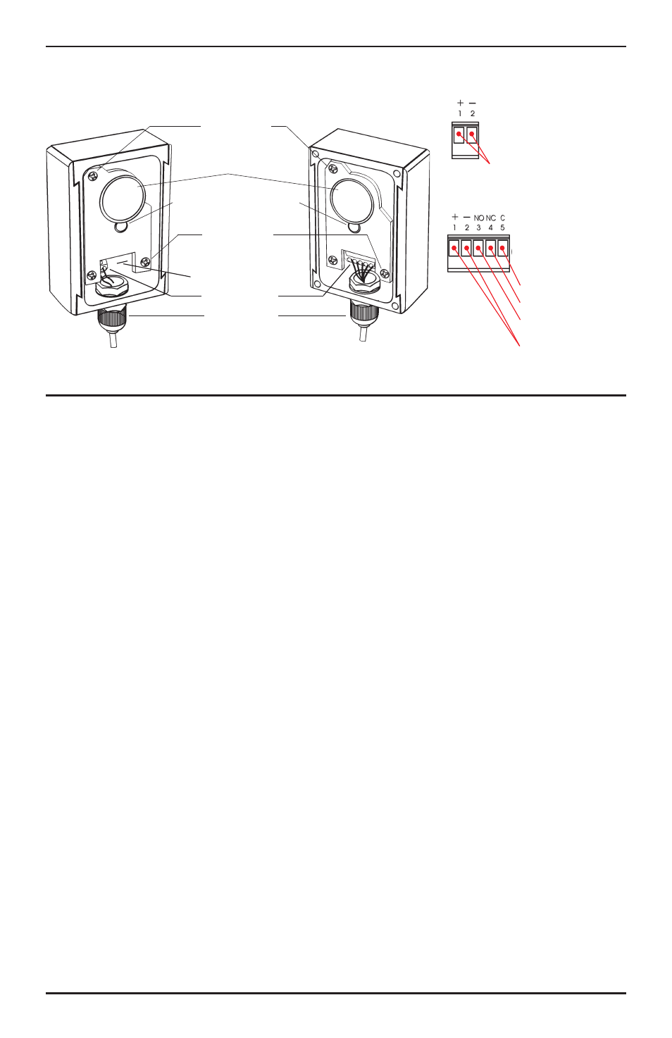
Fig. 6 - Wiring and Adjusting
Installation and Alignment:
LED functions:
GREEN LED – When ON, indicates power is present.
RED LED
– When ON, indicates the sensor is
aligned properly.
When OFF, indicates the sensor is not
aligned properly, or the beam has
been interrupted.
Installation:
1. Install one cable gland in the bottom of the
transmitter, and one in the bottom of the receiver:
a. Remove the lens cover.
b. Carve out the holes in the transmitter and
receiver with a sharp tool.
c. Take the lock nut off the cable gland (see fig. 3),
insert the cable gland into the hole from the
bottom, and tighten with the lock nut.
2. Wire the unit – Run the wires to where the sensor is
to be mounted. Keep wires hidden where possible,
and expose them only at the very end where needed
to connect to the transmitter and receiver. (see fig.6)
3. Decide where to mount:
a. The transmitter and receiver should be facing
each other.
b. The units should not interfere with normal
movement around the protected area.
4. Initial test – Temporarily hold the transmitter and
receiver to the wall where they are to be mounted and
power up the units to test alignment before
permanent mounting. (See Power and Alignment
below.)
5. Mount the transmitter/receiver (flush mount) (fig. 5)
– Mount flush to the wall with three mounting
screws (not included).
6. Mount the transmitter/receiver (perpendicular mount)
(fig. 5):
a. Depending on how mounted, remove one of the
two side brackets.
b. Screw the side bracket into the wall using two
mounting screws (not included).
c. Slide the transmitter or receiver onto the side
bracket.
Power and Alignment
1. Power up the transmitter and receiver. The green LED
on the transmitter should turn ON to indicate power is
present. The red LED on the receiver should turn ON
to indicate the two are aligned properly.
2. Alignment – If the receiver is connected to power, and
if the red LED does not turn on while the green LED is
on, the transmitter and receiver are not aligned.
Loosen or tighten the horizontal and vertical
adjustment screws on the transmitter and/or receiver
until the red LED turns on, indicating alignment.
(Fig. 6.)
NOTE – If two or more E-961-S90W pairs are
installed within close proximity of each other, adjust
the sensor beam brightness to “low” by cutting the
wire loop on the transmitter circuit board just above
the “TX” marking.
Testing:
1. Do a walk-through test. Walk between the transmitter
and receiver. This should break the beam, turn the
red LED off, and trigger the alarm panel or warning
device.
2. Replace the lens covers on the transmitter and
receiver. Test again one last time.
Vertical
Adjustment
Screw
Lens
Horizontal
Adjustment
Screw
Cable Gland
Green
LED
Red
LED
+
- NO NC C
OM
Transmitter
Receiver
Wiring Block
Transmitter
Receiver
Tx Power Setting
C
Relay Output - COM
Relay Output - N.C.
Relay Output - N.O.
10-24VAC/VDC,
Polarity not important
10-24VAC/VDC,
Polarity not important