Operator preparation, Gear reducer vent plug, Limit cam adjustments – Controlled Products Systems Group SG-TB-25-211 User Manual
Page 7
SG
• SG-D Barrier Gate Operator Installation Guide
- 5 -
P1277 Revision X2 8-11-2011
Operator Preparation
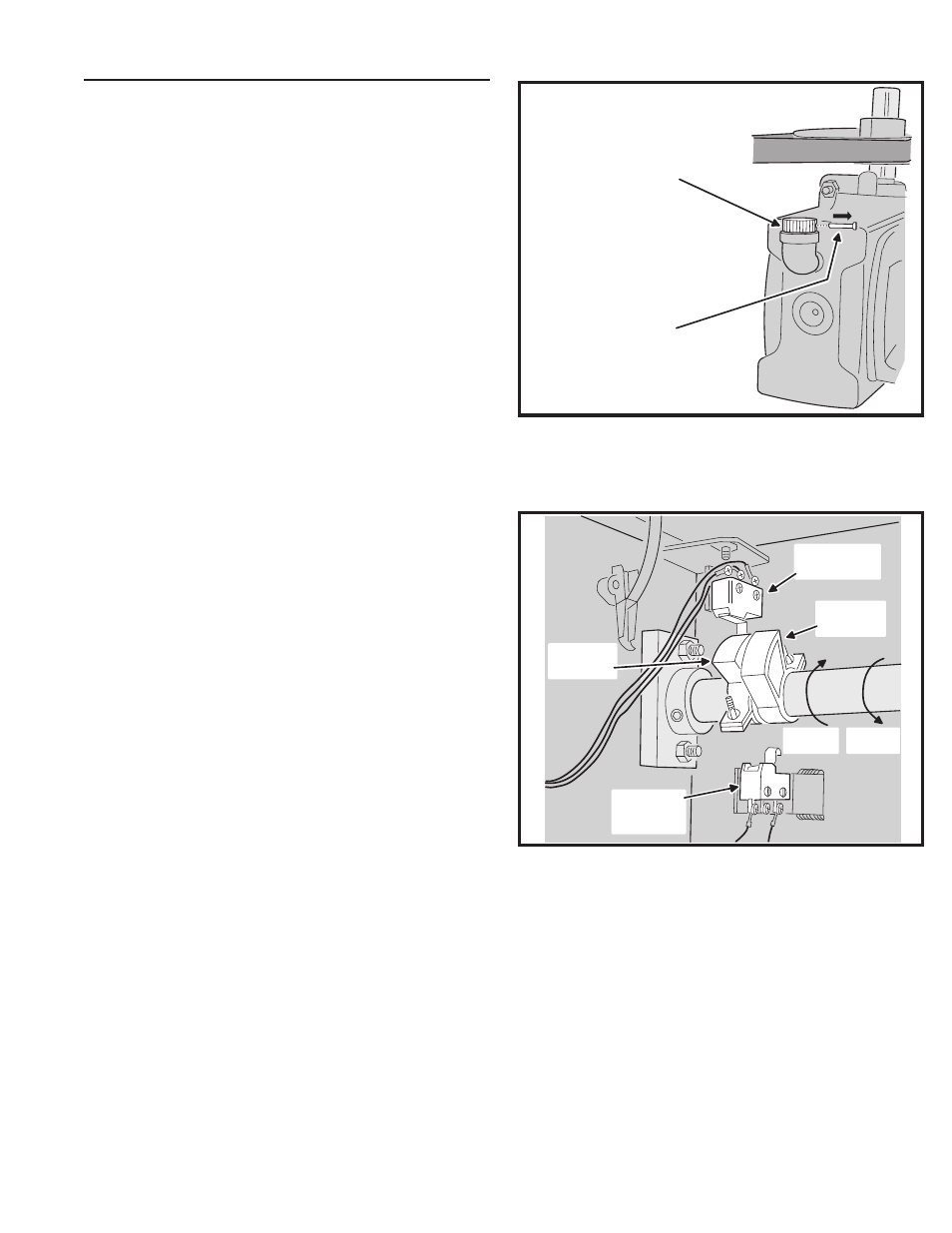
Gear Reducer Vent Plug
In order to keep gear oil from spilling out during shipping,
gear reducers used in the SG and SG-D barrier gate
operators have a sealed vent plug installed at the factory.
Leaving the vent plug installed, remove the vent plug’s
breather pin to allow the gear box to vent (see Figure 5).
The breather pin can be discarded.
Limit Cam Adjustments
The limit cams for all models of barrier gate operators have
been pre-set at the factory for approximately 90 degrees of
motion. If you need to adjust this further, see Figure 6 and
follow the directions below.
1. For
more downward travel, loosen the wingnut on the LSC-1 (down)
limit cam and rotate the cam slightly in the “B” direction.
2. For
less downward travel, loosen the wingnut on the LSC-1 (down)
limit cam and rotate the cam slightly in the “A” direction.
3. For
more upward travel, loosen the wingnut on the LSO-1 (up) limit
cam and rotate the cam slightly in the “A” direction.
4. For
less upward travel, loosen the wingnut on the LSO-1 (up) limit
cam and rotate the cam slightly in the “B” direction.
✓ NOTE: If the barrier gate operator has been custom
confi gured by the factory for reverse arm operation
(where the closed barrier arm sticks out from the service
door side of the operator) the limit switches shown in
Figure 6 will be reversed. The top limit switch will be the
open limit, the bottom limit switch will be the close limit.
GEAR REDUCER
VENT PLUG
REMOVE THE
BREATHER PIN
CLOSE LIMIT
SWITCH LSC-1
CLOSE
LIMIT CAM
OPEN LIMIT
SWITCH
LSO-1
OPEN
LIMIT CAM
DIRECTION
"B"
DIRECTION
"A"
Figure 5. Vent Plug Installation
Figure 6. Limit Cam Adjustment