Warning, Installation on concrete curb – Controlled Products Systems Group SG-TB-25-211 User Manual
Page 5
SG
• SG-D Barrier Gate Operator Installation Guide
- 3 -
P1277 Revision X2 8-11-2011
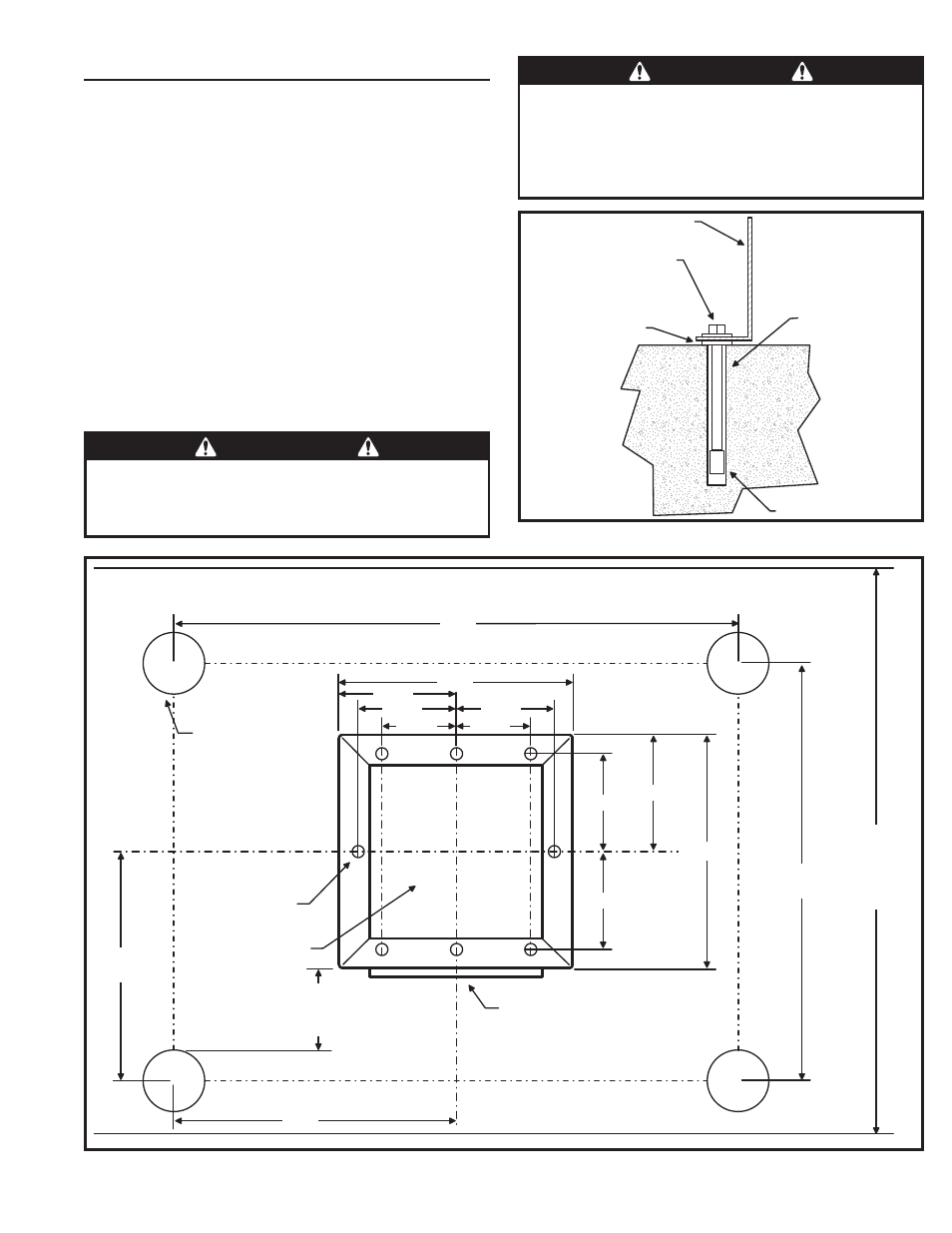
Installation on Concrete Curb
The barrier gate operator bolts to a concrete island or curb.
1. Un-crate the gate. Avoid damaging the cabinet fi nish.
2. Leave the machine bolted to the bottom pallet until ready to install.
3. Open the cabinet door.
4. Remove the bolts holding the gate to its pallet and place the machine
in position on the curb. Refer to your Equipment Layout (EL) drawing
for proper positioning of your gate.
5. With a pencil, mark the location of the mounting holes on the concrete.
6. Set the gate aside. Drill all four mounting holes using a 3/4” diameter
rotary hammer percussion drill bit. Insert lag screw anchors for 1/2”
lag bolts. Place the gate back in position, and anchor it with 1/2” lag
bolts and fl at washers. Lubricate the bolts before installation. Flat
washers have been supplied to go between pavement and cabinet.
Linear highly recommends using the corner mounting holes when
mounting barrier gates.
7. Proceed with the rest of the installation process.
48"
ISLAND
WIDTH
(MINIMUM)
48"
36"
24"
24"
4" DIA. GUARD POSTS
4 FT. TALL, BY OTHERS
15"
7-1/2"
6-1/4"
4-3/4"
4-3/4"
6-1/4"
6-1/4"
6-1/4"
7-1/2"
15"
.75 ø 8X
OPEN SPACE FOR
CONDUITS HERE
SERVICE DOOR SIDE
OF BARRIER GATE
(FACES AWAY FROM DRIVE)
14" MINIMUM
TO PROVIDE CLEARANCE FOR
FLANGE AND COUNTERWEIGHTS
Figure 1. Concrete Lag Anchor Detail
Figure 2. Barrier Gate Mounting Specifi cations
WARNING
The operator is intended for installation only on gates used for
vehicles. Pedestrians must be supplied with a separate access
opening. The pedestrian access opening shall be designed to
promote pedestrian usage. Locate the gate such that persons
will not come into contact with the vehicular gate during the
entire path of travel of the vehicular gate.
WARNING
The gate must be installed in a location so that enough
clearance is supplied between the gate and adjacent
structures when opening and closing to reduce the risk of
entrapment.
CABINET BASE
1/2
ø
X4" LAG BOLT
AND FLAT WASHER
SUPPLIED
FLAT WASHER
3/4ø HOLE
IN CONCRETE
LAG SCREW
ANCHOR