Photo eye sensor placement, Safety loop system installation – Controlled Products Systems Group RAM2000 User Manual
Page 11
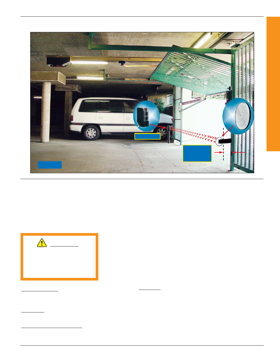
PHOTO EYE SENSOR PLACEMENT
9
RAMSET
RAM 2000 UL
- 2100 UL
- 2200 UL
Figure 7
SAFETY LOOP SYSTEM INSTALLATION
Ramset Gate Operators should not
be installed without non-contact
sensing devices such as Loop
Detectors, Photo Electric Sensors or
the equivalent.
A non-contact sensor (photoelectric
sensor or equivalent) and a contact
sensor (edge device or equivalent)
is required on each individual
installation to comply with UL325.
Reversing Loops on the ground floor,
prevents gate from closing when vehi-
cle is in loop area.
Exit Loops on the ground floor, opens
gate when vehicle crosses loop area.
Photoelectric Safety Sensor
(Photo Eye) prevents the gate from
closing when any object interrupts
the beam.
INSTRUCTIONS:
Mark the loop layout on the pavement.
The pavement is typically cut to a
depth of approximately 1 1/2" to 2"
using a 1/4" wide blade. The slot is
then cleaned with water and then
blown out with compressed air. This
will assure that all sharp particles are
removed from the slot. The corners of
all square or rectangular loops should
have 45º cuts to prevent sharp cor-
ners from puncturing the loop wire.
The turns of wire are then installed in
the bottom of the slot and held into
place with foam backer rod. This will
assure that the wire is held in place
when the sealant is added to the slot.
Loop wires should be twisted at least
8 to 10 turns per foot from the point
where they leave the loop and start
toward the side of the roadway-down
the lead-in slot. The sealant used in
the loop and lead-in slot should be pli-
able and should "give" with tempera-
ture changes in the pavement.
The roadway loop shown in figures 8
and 9 is a typical configuration for a
street or roadway installation. The two
wires leave the rectangular loop and
are placed in another slot to exit the
roadway. The wires used in the main
loop and the exit slot must be one
continuous piece. No splices can be
made in any part of the installation.
Apply sealant to whole sawcut as well
as the main loop. The wires are then
spliced to the lead-in cable at the con-
crete pull box. All splices must be sol-
dered! Do Not Use wire nuts or
crimp type connectors! Tinned cop-
per crimped connections can be used
to hold the wires together as log as
they are then soldered!
The top of the backer rod should be at
least 1" below the level of the pave-
ment.
www.ramsetinc.com
Photo Eye
Reflector
6" Clearance
from spring
WARNING:
6"
TO LINE UP
WITH EACH OTHER