Master/slave connection, Positive to positive, Negative to negative – Controlled Products Systems Group AOMSL1501HPDC User Manual
Page 20: Master board slave board, Slave switch only on slave board on
19
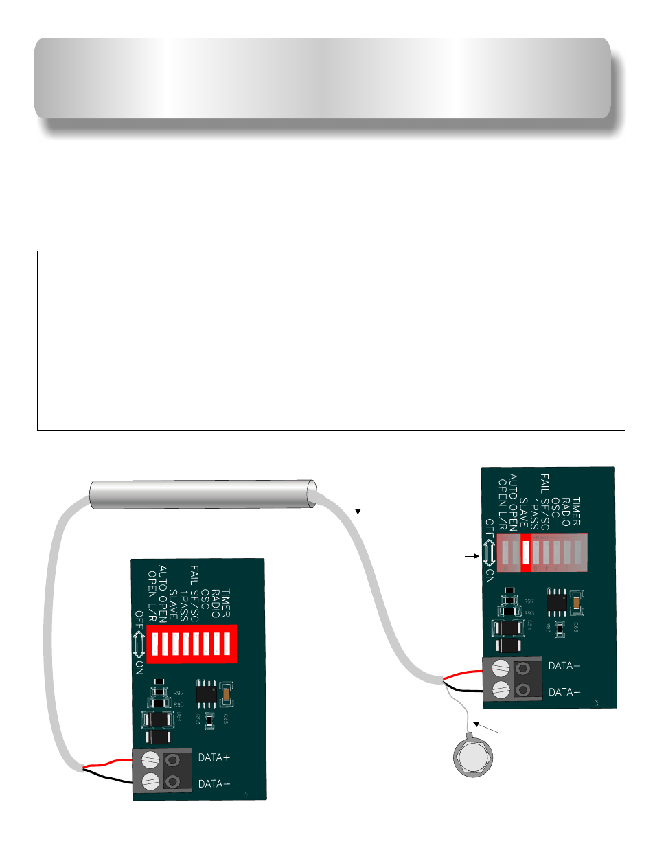
MASTER/SLAVE CONNECTION
Use a two wire
shielded cable and run it through a UL listed conduit for master/slave connection.
Follow the wiring diagram as shown below.
Master Board Slave Board
+.....................Positive to Positive...................+
-...................Negative to Negative...................-
Before connecting master/slave gate operators together, test and adjust the limit switches and the ERDs
for each operator as “stand alone” machines. All accessories must be installed on the master board, no
exception.
See page 22 for dip switch settings.
Connect shield to
slave metal frame
only.
Use UL listed
conduit
Shielded
cable
1
3
5
8
2
4
6
7
---
---
-
---
--
---
--
OP
EN
---
--
---
--
---
-
---
-
--
--
-
-
-
-
-
--
-
C8
RB
LM
C6
4
I
82
AM
1210
0
10 1
1 0
0 1
1
0
0
2
1
7 0
.
KE
1
7 0
K .
E
3
5
1
2
4
6
7
8
---
---
---
-
---
-
OP
N
---
-
---
-
---
---
---
--
--
--
E
--
--
--
---
-
C8
RB
LM
C6
4
82
AIM
0
121
1 0
0 1
1 01
0
0
1
0
2
1
7 0
.
KE
1
7 0
.
KE
Master Board
Slave Board
Slave switch
only on
slave board
ON