Accessory connections, Common n/c n/o, 12 3 rs – Controlled Products Systems Group AOMSL1501HPDC User Manual
Page 15
14
C
C
Power
Power
Detect
Detect
Loop Fail
Loop Fail
Reset
Reset
2
2
1
1
0
0
0
0
SENS.
SENS.
LEVEL
LEVEL
BOOST ON
BOOST ON
PULSE
PULSE
FREQ.
FREQ.
0
0
0
0
OFF
OFF
PRES
PRES
2
2
1
1
11
22
33
44
55
66
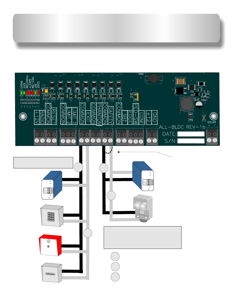
SAFETY Loop
Detector
PHOTO Beam
EXIT
Loop
Detector
Keypad
or
Telephone
Push Button
or
Fire Box
Card Reader
or
Key Switch
See page 12 for connection of
multiple safety device wiring
diagram.
See page 16 for plugin loop
detector installation.
Remove wire jumper
from
when
a safety device is
installed.
SAFETY
ACCESSORY CONNECTIONS
AB
= NORMALLY OPEN CONTACT
N/C
= NORMALLY CLOSED CONTACT
C
= COMMON
N/C
N/O
The circuit board
output provides up to
mAmps of power for accessories. More
than two or three accessories will require a separate power supply.
12VDC Accessories only.
12-VDC
500
NOTE:
Power
Power
Detect
Detect
Loop Fail
Loop Fail
Reset
Reset
2
2
1
1
0
0
0
0
SENS.
SENS.
LEVEL
LEVEL
BOOST ON
BOOST ON
PULSE
PULSE
FREQ.
FREQ.
0
0
0
0
OFF
OFF
PRES
PRES
2
2
1
1
11
22
33
44
55
66
1
ABC
2
DEF
3
GHI
4
L
JK
5
MNO
6
PQRS
7
TUV
8
WXYZ
9
TONE
*
R
OPE
0
#
N/O
C
8
B
R
L
M
6
4
C
8
2
A
IM
2
100
2
100
1002
10 2
0
1
2
00
2
100
2
100
1002
2
100
1
1
2
2
2
2
40
3
0
0
2
6
4
0
0
1
100
20M
10 1
0
1
0
0
1
5
1
1
0
5
1
0
1
1
5
1
0
1
5
0
1
5
1
0
1
1
5
1
0
1
5
0
1
5
1
0
1
1
5
0
1
0
7
1
K
E
.
7
1
0
K
E
.
7
0
1
K
E
.
7
0
1
K
E
.
7
1
0
E
K
.
7
1
0
E
K
.
7
0
1
K
E
.
7
0
1
K
E
.
7
0
1
K
E
.
M
A
A
F
2
B
S
1
6
8
3
C
o
ilc
ra
ft
V
3
3 F
H
K
5
G
N
80
2
36
0G
B
ON
D
R
1
2
7
-3
3
0
0
4
3
C
L
7
E
1
2
3
RS