General loop installation guidelines – Controlled Products Systems Group AOMSL1501HPDC User Manual
Page 14
The following loop installation guidelines are for installing typical driveway loops for access
control applications (i.e. parking gates, sliding gates, swing gates etc...) Always consult withl
loop detector manufacturers for specific equipment guidelines. This will confirm that the
proper configuration and installation techniques are properly applied for your application.
Useful information about inductive loops:
A. The typical sensing height is 2/3 of the shortest leg of loop (in feet)
Therefore a 4’ x 8’ loop typically has a detection height of 2.6’.
B. The inductance of a conventional four-slide loop can be estimated
using the formula:
L = P x (T + T) / 4 Where L = Loop Inductance in microHenries
P = Loop Perimeter in feet
T = Number of turns of wire in saw slot
Therefore a 4’ x 8’ loop with 3 turns would be:
L=(4 + 8 + 4 + 8) x (3 + 3) / 4
L=24 x (9 + 3) / 4
L=24 x 12 / 4
L=24 x 3
L=72 microHenries
2
2
}
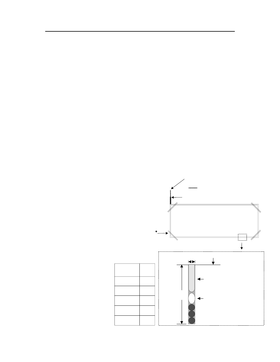
2’’
1/4’’
Saw Slot
Loop Wire: 3 Turns
Backer Rod
Sealant: 3/4’’ to 1’’ Min.
Driveway
Loop
Perimeter
# of
Turns
6’ - 12’ 6
13’ - 20’ 5
21’ - 60’ 4
61’ - 240’’ 3
241 & Up 2
Driveway loop
1/4’’ Feeder Slot
TWISTED 6
TURNS
PER FOOT
45
Angles
Suggested guidelines for loop
installation:
Loop wires should be twisted 6 turns
per foot, and twisted from saw slot to
the detector. If possible start twisting
the wires from the edge of the loop.
All 90 degree corners should be
chamfered so that the course of the
wire does not change direction
sharply but rather at shallower angles
of 45 degrees or less. Core drilling of
the corners achieves the same effect
but can still lead to failure due to
sharp edges remaining in the corner
area.
GENERAL LOOP INSTALLATION GUIDELINES
13