Gate travel adjustment for sl-150dc – Controlled Products Systems Group AOMSL1501HPDC User Manual
Page 10
9
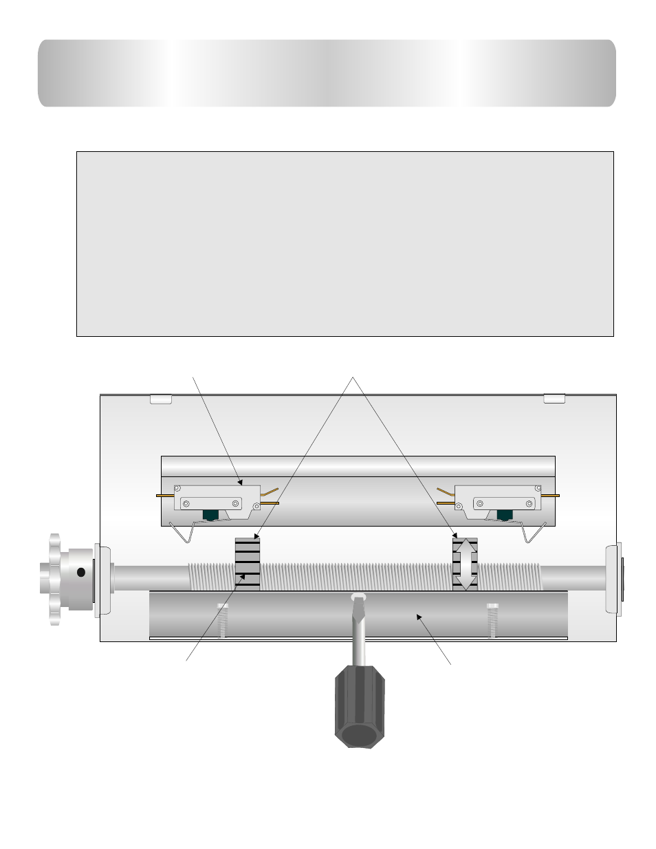
GATE TRAVEL ADJUSTMENT
FOR
SL-150DC
Locate limit switch box.
Step 1: Make sure operator is not running .
Step 2: Use a screw driver to pull limit lock plate outwards. Turn
Limit nut to desired direction.
Step 3: Place limit plate to its locked position.
Step 4: Run the operator.
Step 5: If more adjustment is needed, repeat
the steps (2-3) until desired position is acquired.
Limit nuts
Limit switch
Limit nut lock plate
Each notch equals about ½”
of gate travel.
Limit plate must be tight in limit nut slots for gate to hold it’s
limits.
This manual is related to the following products:
See also other documents in the category Controlled Products Systems Group Safety:
- GNC-1 (1 page)
- -108712 (33 pages)
- 1044372 (28 pages)
- 1042071277 (28 pages)
- 104207177 (28 pages)
- 104301 (30 pages)
- 10441811 (29 pages)
- 1044182 (28 pages)
- 1044682 (28 pages)
- 104471 (28 pages)
- 104572 (24 pages)
- 104572 (27 pages)
- 10468583 (36 pages)
- 1049062 (17 pages)
- 106753 (28 pages)
- 108758 (40 pages)
- 109773 (19 pages)
- 10978021 (6 pages)
- 109902 (27 pages)
- 1150-080 (30 pages)
- 1600 (17 pages)
- 1650ETL (23 pages)
- 1650ETL-1K (32 pages)
- 1601-081 (36 pages)
- 1602-091 (42 pages)
- 1602-091 (42 pages)
- 1603-166 (38 pages)
- 1603-166 (42 pages)
- 1603-166 (40 pages)
- 444 XS ST (98 pages)
- 222X383 (84 pages)
- 3020HX (24 pages)
- 3600ETL-1K (36 pages)
- 4500SW (32 pages)
- 6004-080 (34 pages)
- 6002-080 (32 pages)
- 6003-080 (22 pages)
- 6100-083 (56 pages)
- 6100-083 (2 pages)
- 6100-083 (46 pages)
- 6300-087 (59 pages)
- 6300-087 (52 pages)
- 6400-080 (28 pages)
- 6500-087 (48 pages)
- 6500-087 (46 pages)