Controlled Products Systems Group 8300SL User Manual
Page 9
7
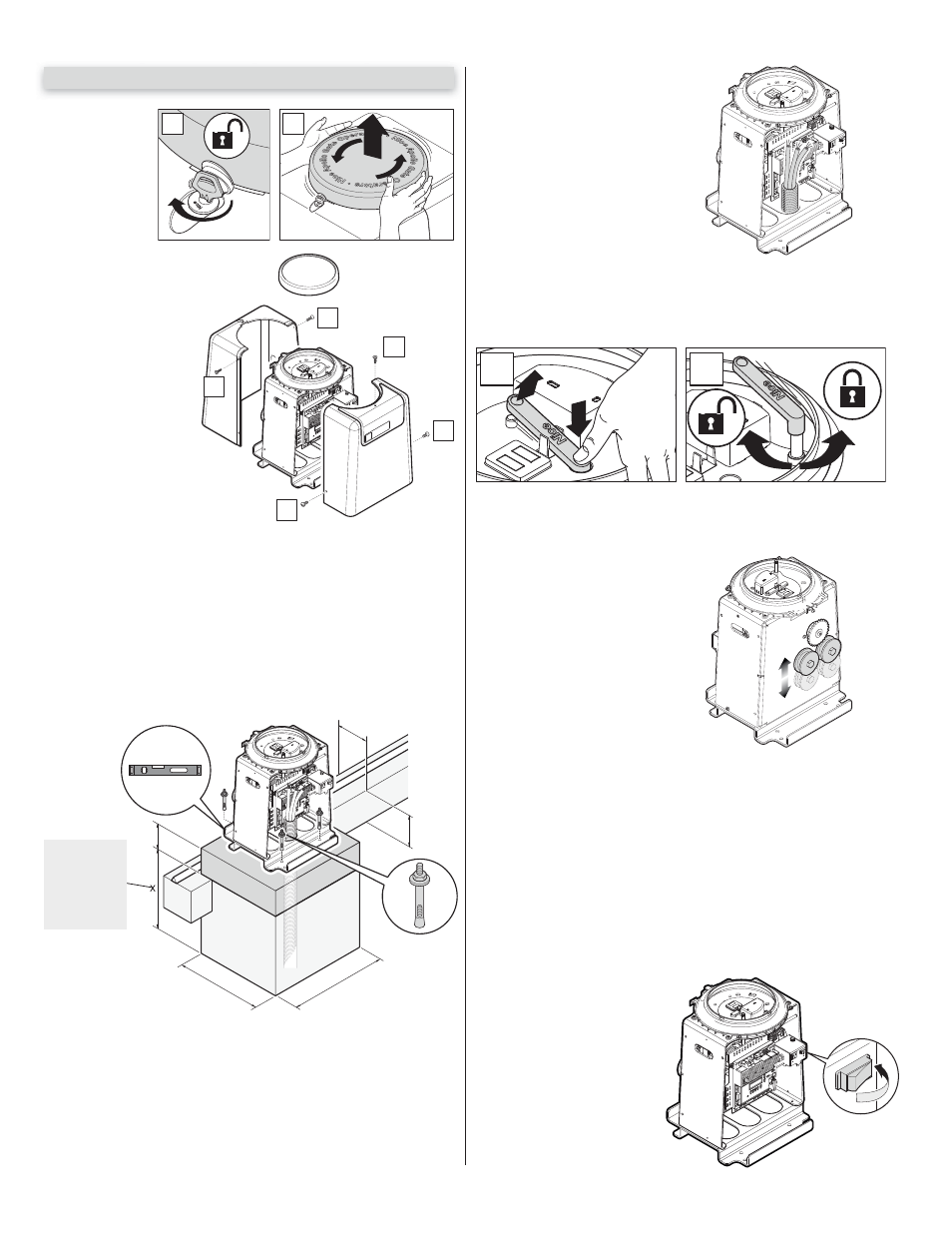
6.4 - Step four-manual release
Locate the manual release handle. Turn the manual release handle counter-
clockwise until the handle stops. The chain drive assembly is now disengaged
and the gate may be operated by hand.
1
2
Figure 6 - MANUAL RELEASE
6WHSƄYHFKDLQDVVHPEO\
Connect Chain assembly to sprocket
assembly and test gate for free move-
ment. (Should move freely in both
directions) Push the gate by hand to
the full movement in each direction
to ensure it does not bind or catch in
@MXL@MMDQ
1DEDQSNjFTQDR@MC
30 for diagrams of correct and incor-
rect installation).
Figure 7 - BRACKET
6.6 - Learning and programming
These steps begin the basic “Learning” programming of the gate opener unit.
Most all of the features and programming are pre-set and already set up for
most standard installations. The installer most often will only be required to
plug the unit into electrical power, connect the chain to the sprocket assembly
and by setting the limits on the gate movement, and then “learning” the unit. In
most cases this is the extent of the basic programming procedure. If the unit
is not in LEARNING MODE see section 6.9 to place the unit into this mode.
Apollo has taken great care to simplify the installation, operation and safety
of this device and to ensure longevity and reliability of the unit over time. The
learning procedure consists of the following steps.
+RZWRVHWXSIRUƄUVWXVH
1. Install electrical power con-
nections to the gate opener
unit. Ensure the power switch
is in the OFF position prior to
touching any of the power
connections. Install all gate
accessories such as Photo-
Eye’s, Sensors, Loops and
other safety devices.
6.1 - Step one-location
Locate the area in which the opener shall be located.
6.2 - Step two-concrete
%@AQHB@SD@BNMBQDSDO@CRSQTBSTQDRTEjBHDMSSNRS@AHKHYD@MCLNTMSSGDF@SD
opener. Please consult the local building dept. and/or a structural engineer to
ATHKC@BNMBQDSDO@CSG@SLDDSRATHKCHMFBNCDR@MCHRRTEjBHDMSENQSGDRNHK
type and climate and capable of supporting the lateral loads imposed by the
NODQ@SNQCTQHMFNODQ@SHNM
2DDjFTQDENQOQNODQHMRS@KK@SHNM
6.3 - Step three-physical mounting
Drill and insert Redhead (1/2” x 3 1/3”) concrete anchors into the concrete
RTEjBHDMSSNOQNODQKXLNTMSSGDF@SDNODMDQ
,NTMSHMFONRHSHNMLTRSAD@
minimum distance of 4 inches distance between the gate and center chain
CQHUDROQNBJDS
1DEDQSNjFTQD.ODMSGDSNOBNUDQTRHMFSGDRTOOKHDCJDX
1DEDQSNjFTQD
1DLNUDSGDSNO@MCRHCDBNUDQRSNF@HM@BBDRRSNLNTMS-
ing holes. Set the unit in place and attach wiring as indicated in the wiring
section 9.0 Wiring and Connections of this manual.
10”
8”
x 4
6”
24”
20”
6 - INSTALLATION PROCEDURES
3
3
1
2
2
0
I
Figure 3 - COVER REMOVAL
Remove side bolts and
covers to access interior
for installation.
Remove gate operator
cover screws accor-
ding to the numbered
sequence as shown.
1
2
1. Remove top
cover assembly by
unlocking the lid
with the supplied
key.
2. Turn lid counter-
clockwise then
remove.
MAKE SURE ALL POWER IS
DISCONNECTED PRIOR TO
ANY SERVICE OR INSTALLA-
TION.
Figure 5 - WIRING
BELOW
THE FROST
LINE
CHECK
ALL LOCAL
CODES
Figure 8 - SETTING UP POWER
Figure 4
SAMPL$+ 8.43