Controlled Products Systems Group 8300SL User Manual
Page 10
8
2. Using the MANUAL RELEASE HANDLE, Move it counter-clockwise to dis-
engage the drive motor. Ensure that the gate moves freely by moving it
manually to the full extents of its travel in both directions verifying there is
no binding or cause for resistance.
3. Using the MANUAL RELEASE HANDLE, move it clockwise to re-engage
the drive system and then stow the handle.
1
3
2
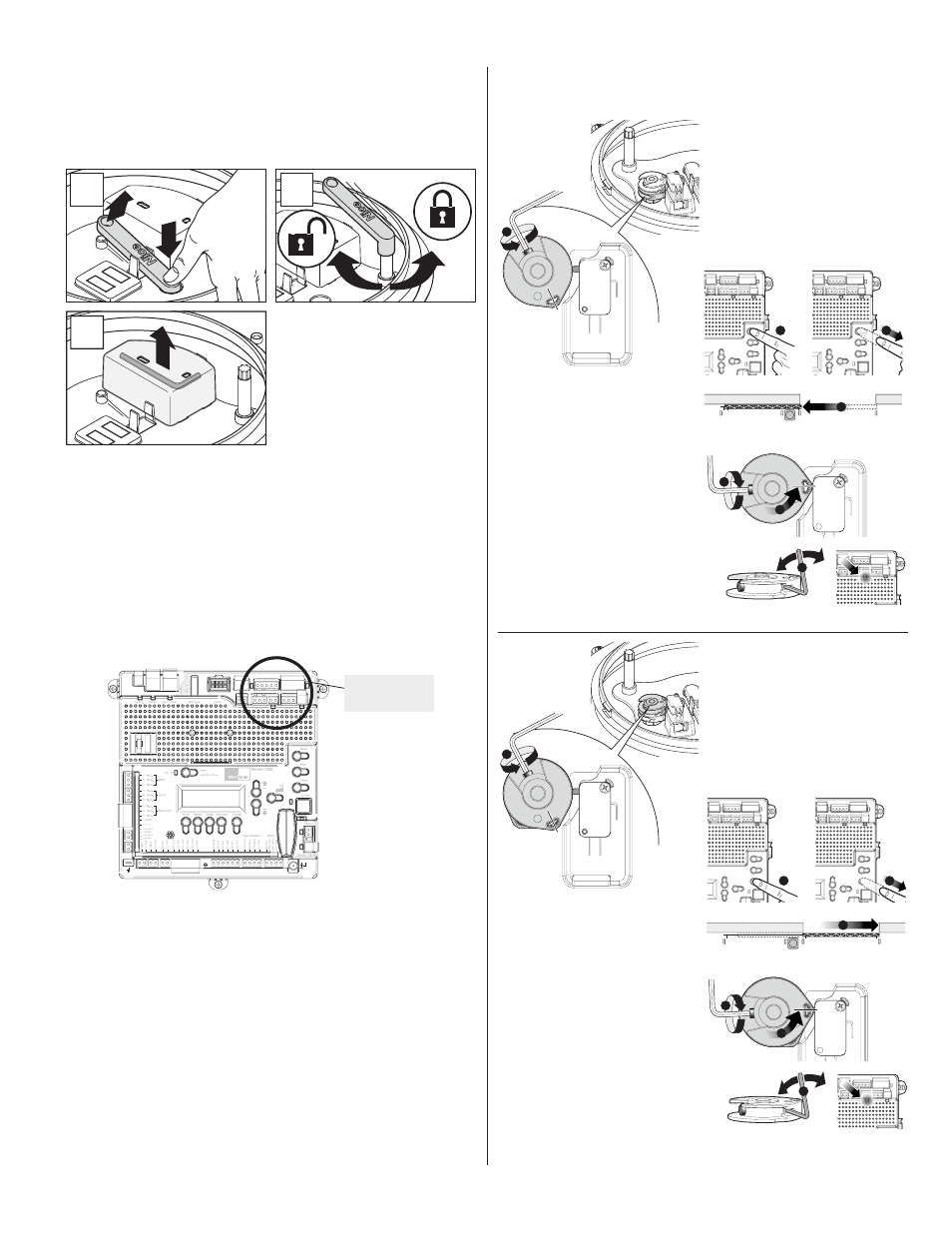
Figure 9 - MANUAL RELEASE
4.1DLNUDSGD KKDMJDXHMRHCDSGDKHCOG@RDjF @MCSGDMKNNRDMSGD
FQTARBQDVNESGDB@LROG@RDjF
RNSG@SSGDXB@MADSTQMDCEQDDKX
by hand.
5. Turn on the electrical power to the unit.
6. Using the OPEN button on the front of the Control board, hold the OPEN
button down until the gate reaches the fully open position or where the
HMRS@KKDQV@MSRSGDF@SDSNRSNO@R%4++8./$-RDDjFTQD
(ESGDF@SD
moves the wrong direction, refer to section 16.0 to reverse the direction.
7..MBDSGDF@SDHRHMSGDONRHSHNMVGDQDSGDF@SDHRHMSDMCDCSNADf%4++8
OPEN” the OPEN limit switch must be adjusted to inform the circuit board
that the gate is in the correct position to STOP at that position in the future.
CLOSE/OPEN
INDICATOR
Figure 10 - INDICATOR LIGHT
3N@CITRSSGD./$-KHLHSRVHSBGNMSGD+.6$1" ,RDDjFTQD@MC
@[email protected]+HLHS2VHSBG" ,TMSHKSGD&1$$-KHFGSRDDjFTQDHKKT-
LHM@SDRNMSGDEQNMSNESGDBNMSQNKAN@QC
3GD%4++8./$-KHLHSRVHSBGHR
MNVRDS
'NKCHMFHSjQLKXHMOK@BDTRDSGDRTOOKHDC@KKDMVQDMBGSNSHFGSDM
the set screw.
8. Using the CLOSE button on the front of the Control Board, hold the CLOSE
button down until the gate reaches the fully intended closed position. Once
SGDF@SDHRHMSGD%4++8(-3$-#$#"+.2$#ONRHSHNMNMSGD4//$1" ,
RDDjFTQD@MC@CITRSSGD"+.2$#+HLHS2VHSBG" ,TMSHKSGD1$#
KHFGSHKKTLHM@SDRNMSGDEQNMSNESGDBNMSQNKAN@QC
3GD%4++8"+.2$#KHLHS
RVHSBGHRMNVRDS
'NKCHMFHSjQLKXHMOK@BDTRDSGDRTOOKHDC@KKDMVQDMBG
to tighten the set screw.
9.#TQHMFSGDBNTQRDNEHMHSH@KRDSTO@jMD@CITRSLDMSNESGDKHLHSRVHSBGL@X
ADQDPTHQDC
$@BGKHLHSRVHSBG" ,G@R@jMD@CITRSLDMSRBQDVATHKSHMSN
allow the installer to make very small incremental adjustments to ensure the
gate reaches the exact position desired. This feature is used after operating
SGDF@SDSNjMDSTMDSGDDW@BSRSNOOHMFONHMS
2DDRSDOHM%HFTQD@MC
Figure 12.
%HFTQD%4++8./$-+(,(326(3"'
6
5
7
1
3
2
4
%HFTQD%4++8"+.2$#+(,(326(3"'
6
5
7
1
3
2
4