5 - exit and edge inputs wiring diagram, 6 - radio receiver connection (third party), 3 - magnetic lock connection – Controlled Products Systems Group 8300SL User Manual
Page 15: 4 - guard station connection
13
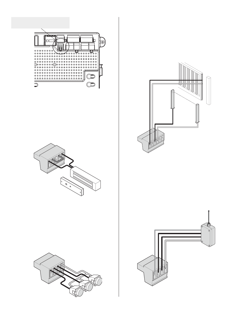
10.5 - Exit and edge inputs wiring diagram
28 EDGE
29 GND
30 EXIT
31 GND
3GD$#&$HMOTSL@XADBNMjFTQDC@R@LNMHSNQDC - +.&HMOTSNQ#(&(-
TAL (NC or NO) input. The EDGE sensor input is intended for ANSI/UL 325
listed gate edge sensors to protect against entrapment and hazardous pinch
points along the moving edge of the closing gate. The EXIT sensor input is
provided to activate to open the gate, or re-open a closing gate, upon sens-
ing an exiting vehicle.
Figure 24 - EXIT AND EDGE INPUTS
10.6 - Radio receiver connection (third party)
38 12V
39 OPEN
40 CLOSE
41 GND
The customer supplied radio receiver allows the gate operator to be operated
via remote, such as wireless key-card readers or user remote controls. Con-
necting the Open (39) and Close (40) pins together with a receiver enables
RHMFKDATSSNMF@SDBNMSQNK
3GHRBNMjFTQ@SHNM@KKNVR@RHMFKDATSSNMSNBNMSQNK
the gate in the following sequence:
Press - Gate Open
Press - Gate Stop
Press - Gate Close
Press - Gate Stop
Figure 25 - RADIO RECEIVER CONNECTION
Figure 21 - FAIL SAFE CONNECTION
10.3 - Magnetic lock connection
7 NC
8 Com (Common)
9 NO
10 GND
11 V+
This connection is used to install the magnetic lock. In this instance a gate
can be locked magnetically to prevent a forced opening. Connections to this
L@XADCHEEDQDMSSG@MRGNVM
"NMRTKSKNBJL@MT@KENQRODBHjBRNMHMRS@KK@SHNM
and wiring.
Figure 22 - MAGNETIC LOCK
CONNECTION
10.4 - Guard station connection
34 OPEN
35 STOP
36 CLOSE
37 GND
With a Guard Station switch in place, a user could operate the gate by push-
ing the respective buttons for the command that is desired. Gate Open, Stop,
@MC"[email protected], ++8./$--.@MC
-.1, ++8"+.2$#-"LNLDMS@QXRVHSBGDR
NOTE: If guard station inputs are not used, STOP (35) and GND (32) need
to be tied together.
Figure 23 - GUARD STATION
CONNECTION
*36:,
:;67
67,5
56
5*
56
Fail Safe connector with jumper installed on
the Primary motor control connectors
28
29
30
31
32
33
38
39
40
41