Controlled Products Systems Group 8300SL User Manual
Page 14
12
9 - WIRING AND CONNECTIONS
Permanent wiring is to be employed for the installation as required by
local codes.
Use only U.L. listed (or equivalent) non-contact sensors. Inputs from the pho-
to-beam to the circuit board are Normally Open (N.O.). Use only U.L. listed (or
equivalent) non-contact sensors.
Connect the non-contact sensors. Inputs from the photo-beam to the circuit
board are Normally Open (N.O.). Photo-beam input shall REVERSE travel of
F@SDVGDM@BSHU@SDCCTQHMFSGD"+.2$"8"+$.-+8
&@SDVHKKQDRTLDMNQ-
mal operation when photo-beam is no longer activated.
3NQDCTBDSGDQHRJNE2$5$1$(-)418NQ#$ 3'
q #HRBNMMDBSONVDQSNSGDF@SDNODQ@SNQAXL@MT@KKXNODMHMFHSRCDCHB@SDC
circuit breaker before making any mechanical or electrical adjustments.
q 4RD@ LOCDCHB@SDCBHQBTHSAQD@JDQENQD@BGHMRS@KKDCF@SDNODQ@SNQ
q .ODM CDCHB@SDC BHQBTHS AQD@JDQ RTOOKXHMF ONVDQ SN SGHR F@SD NODQ@SNQ
!$%.1$@MDVHMRS@KK@SHNMNQL@JHMF@MXLNCHjB@SHNMRSN@MDWHRSHMF
installation of this gate operator.
q KKVHQHMFBNMMDBSHNMR,423ADL@CDAX@PT@KHjDCHMCHUHCT@K
q 1TMHMCHUHCT@KBHQBTHSRHMRDO@Q@SD4
+
KHRSDCBNMCTHSR
#NMNSBNLAHMD
high voltage (120VAC) power wiring and low voltage (+12VDC to +24VDC)
control wiring in the same conduits.
q (SHRGHFGKXQDBNLLDMCDCSG@S@FQNTMCHMFQNCADHMRS@KKDCVHSGD@BGNODQ-
ator according to local building codes to provide protection against near
lightning strikes. Contact local underground utility companies BEFORE dig-
ging.
q 4RDSGDHMENQL@SHNMHMS@AKDSNCDSDQLHMDGHFGUNKS@FDVHQDRHYDQDPTHQD-
ments. The distance shown in the chart is measured in feet from the opera-
tor to the power source. If power wiring is greater than the maximum dis-
tance shown, it is recommended that a service feeder be installed. When
large gauge wire is used, a separate junction box must be installed for the
operator connection. The wire table is based on stranded copper wire.
Wire run calculations are based on a 110 VAC power source with a 3%
voltage drop on the power line, plus an additional 10% reduction in dis-
tance to allow for other losses in the system.
Table 1 - Wire Gauges and Maximum Power Circuit Distances
Figure 19 - GROUNDING WIRE
The gate operator should be grounded to a copper rod driven to a minimum
depth of 3 feet, and properly grounded to the opener using a ¼” copper wire
prior to operation. Ensure proper ground bonding by removing paint around
the mounting hole to create a proper connection if required. (Burnishing may
be required) Check conductivity using a multimeter to verify bonding. (Ring-
Out). Use a star washer between the ring terminal and the nut to ensure a
FNNCFQNTMCBNMMDBSHNM
2DDjFTQD
110V AWG
14
12
10
8
6
4
MAX RUN (ft)
180 280 460 700 1150 1800
WARNING
This slide gate operator uses an inherent entrapment sensing system as well
as external type sensors.
WARNING: External entrapment protection must be added to insure a
safe vehicular gate operating system.
Entrapment protection must be provided by a combination of non-contact
inherent devices. Disconnect power to the gate operator before installing the
non-contact sensors.
BST@KOK@BDLDMSNERDMRNQRHRCDODMCDMSNMSGDRODBHjBHMRS@KK@SHNMQDPTHQD-
ments.
One or more non-contact sensors should be located where the risk of entrap-
ment or obstruction exists such as the perimeter reachable by a moving gate
or barrier.
ISOLATE ALL ELECTRICITY PRIOR TO INSTALLATION OR SERVICE
10 - OPTIONAL INPUTS
10.1 - Fire input
32 FIRE
33 GND
#QXBNMS@BSHMOTSENQ@jQDCDO@QSLDMSBNMSQNKRVHSBG
[email protected].
contact must be shorted to ground through a switch to open the gate. Opens
the gate and holds the gate open until the control switch is deactivated. This
input is “hold to run”. Auto-close is disabled when this input is activated. Also
clears hard shutdown.
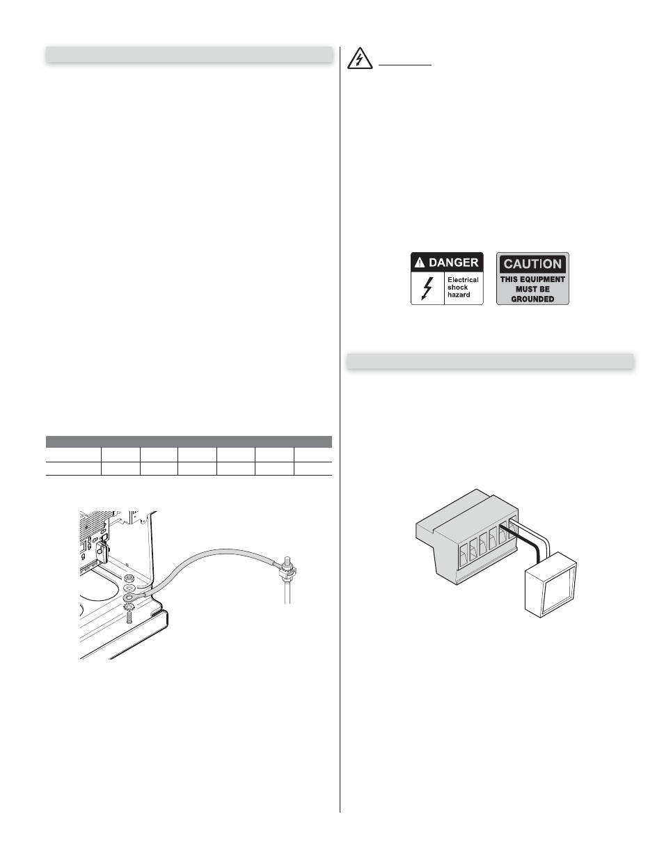
Figure 20 - FAIL SAFE CONNECTOR
10.2 - Fail safe connection
A “fail safe” electric motor brake is provide for each of the three motor control
outputs on the main gate control board. A jumper is installed at the factory for
SGDOQHL@QXLNSNQBNMSQNK@RRGNVMHMjFTQDSN@BSHU@SDSGHRDKDBSQHBAQ@JD
This jumper creates an effective brake action on the motor that does not allow
the gate to be operated (opened or closed) manually, whether or not the gate
operator is powered. This jumper may be removed during a power outage to
enable operation of the gate manually, or during installation, the jumper may
be removed and this connector may be wired to an external switch for more
convenient access. The fail safe jumpers for the Motor 1 and Motor 2 control
provide the same electric brake function for external gate motors in alternative
installations.
-09,
+,7;