Attach the operator to the rear mounting bracket, Attach the operator to the front mounting bracket – Controlled Products Systems Group 104470 User Manual
Page 8
Page 8
January, 200 4
412 O pe rator And
455 D Control Panel I nst allatio n M anual
Outward swinging gate:
If you are installing the 412 Operator to swing the gate
outward, construct a steel elbow of sufficient size to
attach to the gate pillar and rear mounting bracket (see
Figure 7 for elbow dimensions).
A
TTACH
THE
O
PERATOR
TO
THE
R
EAR
M
OUNTING
B
RACKET
Attach the operator to the rear mounting bracket with
the long pin and one snap ring on the bottom (see
Figure 8).
A
TTACH
THE
O
PERATOR
TO
THE
F
RONT
M
OUNTING
B
RACKET
Attach the operator to the front mounting bracket with
the short pin and one snap ring on the bottom and one
snap ring on the top (see Figure 9).
11 13/16 in.
(30 cm)
4 in.
(10 cm)
5 29/32 in.
(15 cm)
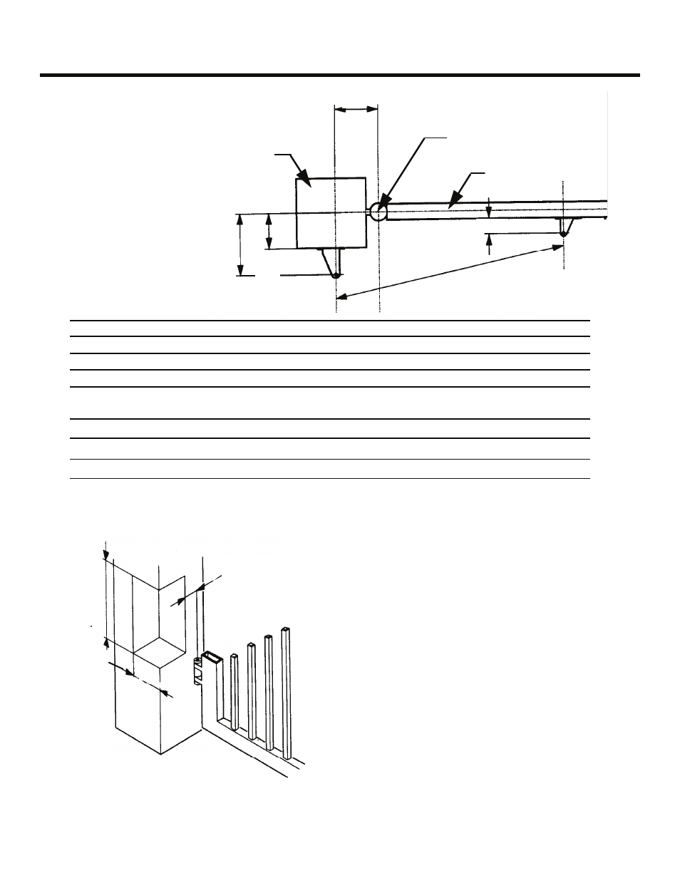
Figure 6. The required dimensions of the recessed liner
when notching the gate post
A
D
B
E
C
F
Gate post
(or column)
Axis of rotation
for gate leaf
Center of gate leaf
Figure 5. Important
mounting dimensions for
inward-swinging 412
operators, top view
Mounting Dimensions
90-deg Swing
110-deg Swing
A
5 3/4 in. (14.5 cm)
4 7/8 in. (12.5 cm)
B
5 3/4 in. (14.5 cm)
4 7/8 in. (12.5 cm)
WARNING! A and B should differ by no more than 2 in. Larger differences may dangerously alter the speed of
operation.
C
36 1/4 in. (89.2 cm)
D
Maximum 4 1/2 in. (10.8 cm)
3 3/8 in. (8.45 cm)
E
Less Than A
Less Than A