Npacking, Perator – Controlled Products Systems Group 104470 User Manual
Page 5
Page 5
January, 200 4
412 O pe rator And
455 D Control Panel I nst allatio n M anual
U
NPACKING
THE
O
PERATOR
When you receive your 412 Compact Operator, complete
the following steps.
Inspect the shipping box for physical damage such as a
torn carton. Then inspect the operator after you remove
it from the box. Notify the carrier immediately if you
note any damage because the carrier must witness the
damage before you can file a claim.
As you unpack the box, insure that all the parts listed
below are included (also see Figure 1). Your kit (a pair of
operators) has these parts:
(1) Control panel enclosure with control panel and
photobeams inside (only 1 per kit).
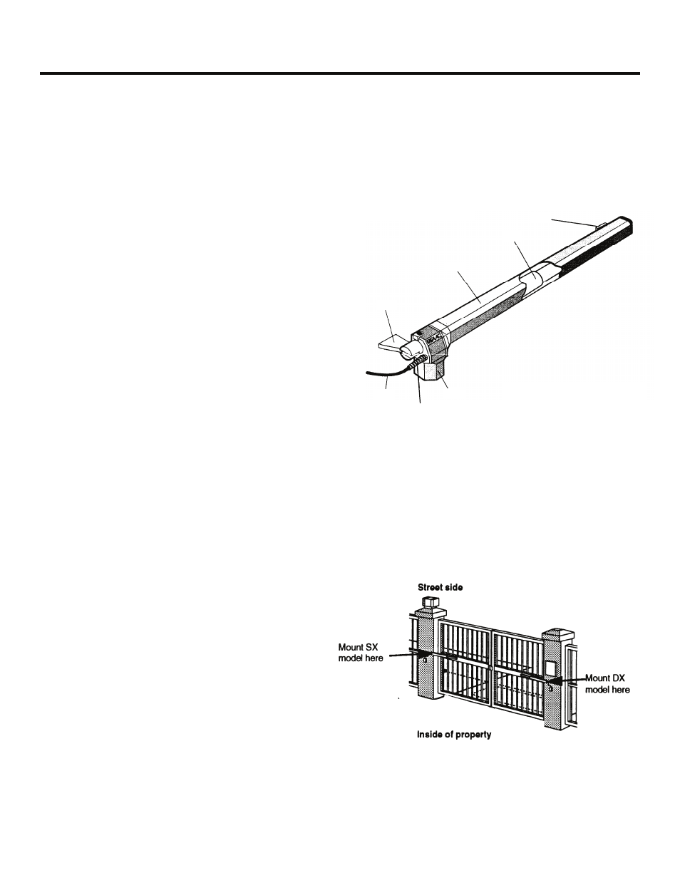
(2) 412 Operator units. One is marked SX and one is
marked DX. Be sure to install each on the proper
gate leaf (see Figure 2).
(2) Protective covers for the worm screw housing of the
operator
(1) Package of mounting hardware:
(2) Rear mounting brackets
(2) Rear mounting plates that attach to the gate
post (or column)
(2) Front mounting brackets that attach the
operators to the gate leaves
(1) Parts package:
(2) Capacitors
(2) End caps
(2) Plastic inserts for the protective cover
(2) Manual Release keys
(2) Plugs for covering the Manual Release keyhole
(6) Snap rings
(4) Screws for attaching the cover to the operator
(2) Long pins for rear mounting (each requires 1
snap ring)
(2) Short pins for front mounting (each requires 2
snap rings)
Figure 1. Parts of the 412 Compact Operator
(SX model is shown)
Front bracket
Worm screw
Cover
Rear bracket
Power cable
Cable cover
Motor
Figure 2. Mount the proper model (SX or DX) on the gate
leaf whether the gate swings inward or outward.