Installing the 455 d control panel, 455 d c – Controlled Products Systems Group 104470 User Manual
Page 10
Page 10
January, 200 4
412 O pe rator And
455 D Control Panel I nst allatio n M anual
I
NSTALLING
THE
455 D C
ONTROL
P
ANEL
Locate the control panel enclosure in the most
convenient position possible, considering the movement
of the gate. Figure 12 shows a basic layout for a two-
leaf gate with the 412 Compact Operator.
Installing the control panel consists of the following
general steps:
•
Connecting the main power to the control
panel
•
Connecting the activating device
•
Connecting the operator to the control panel
•
Checking the direction of the motor's rotation
•
Connecting other devices to the control panel
•
Set operating modes
The installer is responsible for grounding the gate and
operator systems, for providing the main power breaker
switch, and for making sure that the entire gate system
meets all applicable electrical codes.
For the complete 455 D Control Panel Installation
Instructions, see pages 14—25 of this manual.
A
TTACH
THE
O
PERATOR
C
OVER
.
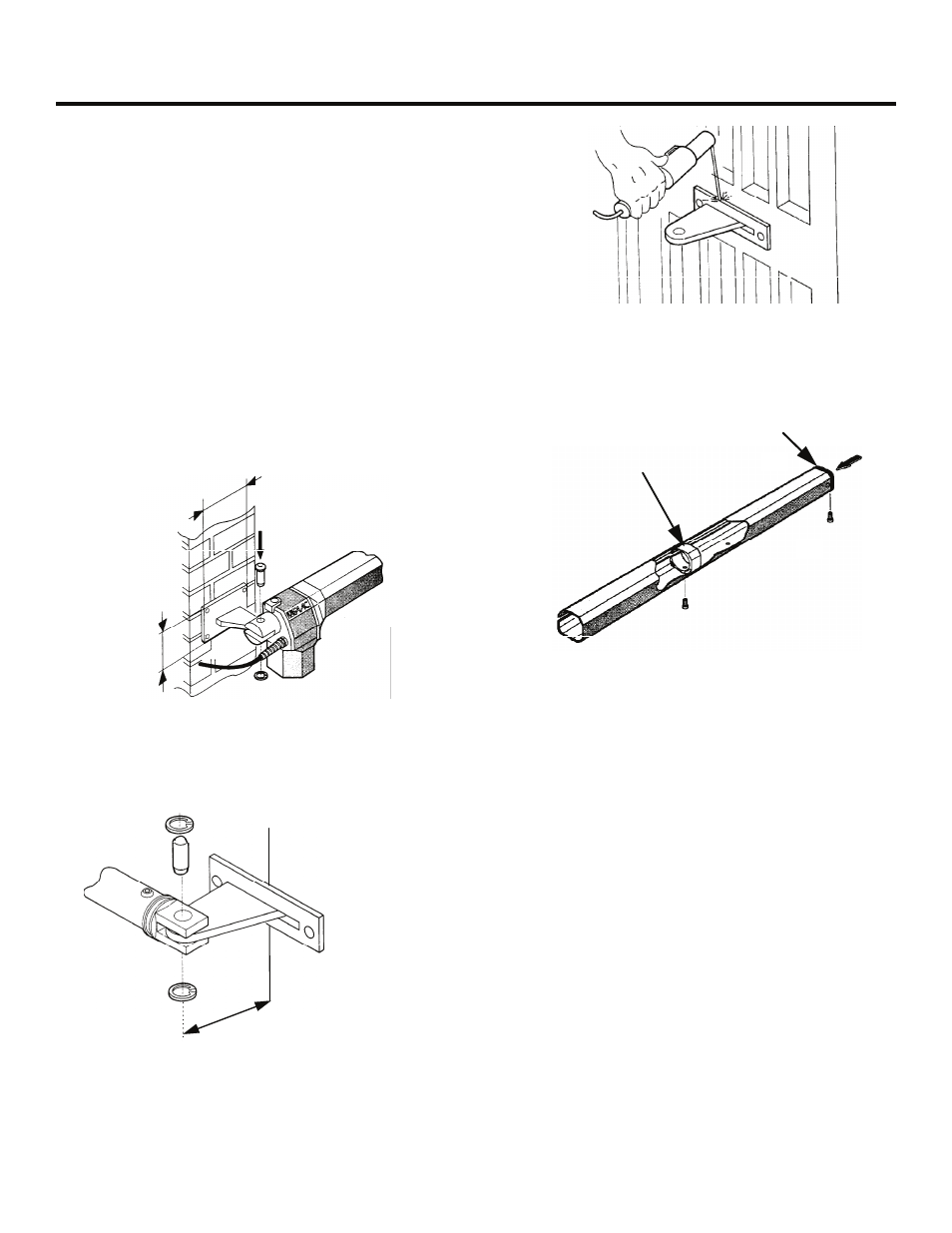
Once the operator is attached to the gate leaf, you
next prepare the cover for installation.
Caution: If you did not correctly establish the
orientation of the gate leaf and properly
install the DX model on the right side and SX
on the left side, you will be unable to install
the cover on either operator.
Position the mounting insert inside the aluminum
cover and then slide the aluminum cover into
position. Secure the cover and insert with the short
screws provided (see Figure 11).
4 3/8 in.
(11 cm)
2 3/4 in.
(7 cm)
Figure 8. Attach the operator to the rear
mounting bracket (an SX version is shown)
Minimum of 3 1/8 in. (8 cm) from
the back of the vertical mounting
plate to the center of the front
mounting hole on the operator
Figure 9. Secure the operator to the front mount-
ing bracket with the short pin and 2 snap rings
Figure 10. Weld the front mounting bracket into position
after insuring the operator is level in the fully closed and
fully opened positions
The plastic cover insert
has a slot that must align
with the slot in the cover
End cap for cover
Figure 11. Attach the cover with two screws (SX
model shown)