Installation programming – Controlled Products Systems Group DL650 User Manual
Page 6
3. Press
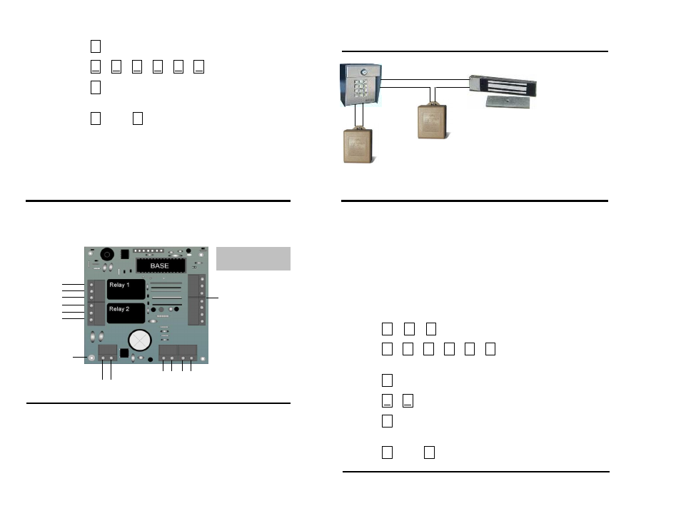
Magnetic Lock Control
4. Press
(new PAC)
5. Press
Response BEEP! BEEP!
6. Press
Then
Response BEEP! BEEP! BEEP!
PROGRAM COMPLET E
Page 10
Page 3
INSTALLATION
PROGRAMMING
Programming the "Strikes and Out" Feature
The "Strikes and Out" Feature tells the system how many incorrect entry codes may
be entered within a three minute period before the system deactivates for three
minutes. When the "Strikes and Out" count has been reached, all keypad input including
access to the programming mode will be ignored for three minutes. The "Strikes and Out"
count is cleared when a valid entry code is entered or the system has not had any input
for 60 seconds. The factory setting is five incorrect entry codes allowed. A setting of
zero may be used to turn this feature off. To change the "Strikes and Out" count:
1. Press
2. Press
(or new PAC)
Response BEEP! BEEP!
3. Press
4. Press
(number of incorrect codes to be allowed 00 to 99)
5. Press
Response BEEP! BEEP!
6. Press
Then
Response BEEP! BEEP! BEEP!
PROGRAM COMPLET E
Programming Entry Code Length
1. Connect NC1 to the Magnetic Lock
power source.
2. Connect COM1 to the Magnetic Lock
Common Input.
3. Connect power source to Magnetic
Lock power input.
3. As shown, a separate power supply
must be used to power the Magnetic
Lock.
0
#
4
#
Magnetic Lock
Magnetic Lock Power
Any device such as an exit button or a Knox Lock may be connected to the
system to operate Relay 1 or Relay 2. A momentary contact closure will cause
the desired Relay to latch for the programmed time. To connect an open device:
1. To activate Relay 1 connect the open device to EXIT 1 and COM.
2. To activate Relay 2 connect the open device to EXIT 2 and COM.
3. Use a two conductor, shielded cable and connect the shield to the
ground screw in the Digi-Lock.
Circuit Board Diagram and Terminal Descriptions
Auxiliary Open Feature
COM 1
NC 1
NO 1
COM 2
NC 2
NO 2
Ground Screw
12 VAC power input. Use supplied
transf ormer, or 12 VDC if desired.
(Input is not DC polarity sensitiv e)
E
X
IT 1
E
X
IT 2
TZO
NE
CO
MM
Slav e Key pad Terminals
(See page 5 f or connections)
Serial Number and
Rev ision Letter are
Under Slav e Key pad
Terminal Block
#
0
0
#
#
#
0
0
0
0
0
3
#
Digi-Lock Power 12V
Digi-Lock Power 12V
Normally Closed
Power
Common
All of the BLUE Terminal
Blocks simply lif t of f of
the
2