Programming installation – Controlled Products Systems Group DL650 User Manual
Page 5
Factory Settings
Listed below are the factory settings for the Digi-Lock:
Function
Factory Setting
Program Access Time
0 0 0 0 0 0
Power Wire Size Guide
Relay Default Time
10 Seconds
Strikes & Out Feature
5 Incorrect Entry Codes
Entry Code Length
4 Digits
Page 2
Page 11
PROGRAMMING
INSTALLATION
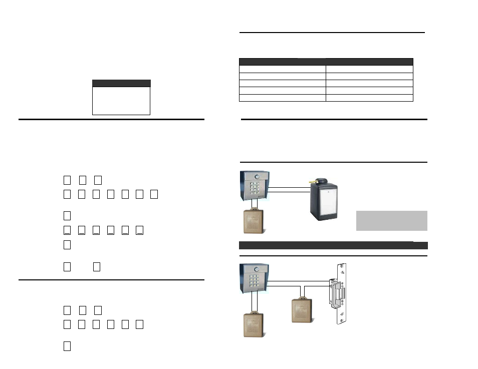
Basic Wiring Configurations
Program Access Code (PAC)
Each system is equipped with two relays that may be used to control a gate, door strike,
The Program Access Code (PAC) is a 6 digit number used to gain access to
magnetic lock, or other device. Refer to the diagrams below when using these
the programming mode. The factory setting is 000000 for each system. To
configurations. (See page 4 for terminal descriptions.)
change the PAC:
Gate Operator Control
1. Press
2. Press
(or new PAC)
Response BEEP! BEEP!
3. Press
4. Press
(new PAC)
5. Press
*** See Important Safety Notice; Inside Cover of this Manual ***
Response BEEP! BEEP!
Electric Door Strike Control
6. Press
Then
Response BEEP! BEEP! BEEP!
PROGRAM COMPLET E
Verifying the Program Access Code (PAC)
To verify the PAC:
1. Press
2. Press
(or new PAC)
Response BEEP! BEEP!
Powering the System
It is important to properly power the system with a good power source. To properly power
the system:
1. Provide power from a dedicated source.
2. Use the 12 VAC, 20va transformer supplied with the system.
3. Use the following guide to determine the proper wire size based upon the distance
from power source to the system.
18 AWG 75 Feet
16 AWG 150 Feet
14 AWG 250 Feet
12 AWG 500 Feet
#
0
0
#
#
#
0
0
0
0
0
0
9
#
#
0
#
#
0
0
0
0
0
Door Strike Power
1. Connect COM1 to the Gate Operator
Common Input.
2. Connect NO1 to the Gate Operator
Open Input.
3. Use at least 18 AWG or larger wire.
1. Connect NO1 to the Electric Strike
power source.
2. Connect COM1 to the Electric Strike
Common Input.
3. Connect power source to Electric
Strike power input.
4. A separate power supply must be
used to power the Electric Strike.
Door Strike
Gate Operator
Digi-Lock Power 12V
Digi-Lock Power 12V
Use the supplied transformer.
DO NOT use power from the
Gate Operator Circuit Board!
Common
Normally Open
Power
Normally Open
Common
2