Figure 2 – otal driver front view, Figure 3 – otal driver rear view, Introduction 6 – CTI Products OTAL On-the-Air Driver Assembly User Manual
Page 6
CTI Products, Inc.
OTAL Driver Assembly User Guide
Note that the external CIB and EXB modules are not part of the OTAL Driver Assembly, and must be
purchased separately.
The OTAL Driver Assembly has the following features:
• Accepts (8) remote COR inputs via MCN network
• Accepts (8) local PTT inputs
• Accepts (8) remote PTT inputs via MCN network
(optional – S1-61030 only)
• Powered by 100-140 VAC input
• Optional 12 VDC input
• Generates (8) On The Air Light (OTAL) Outputs
• Jumper selectable OTAL Logic:
- COR only OTAL
- COR + PTT OTAL
• Keyup Failure Alarm (when PTT is used)
• Link Status (for both IIB modules)
• Power supply status (for both power inputs)
• OTAL and alarm status outputs (via MCN Network) for display on PCs
• Front panel LED display of
-Local & Remote PTT
-COR signals
-OTAL Signals
-Alarm Signals
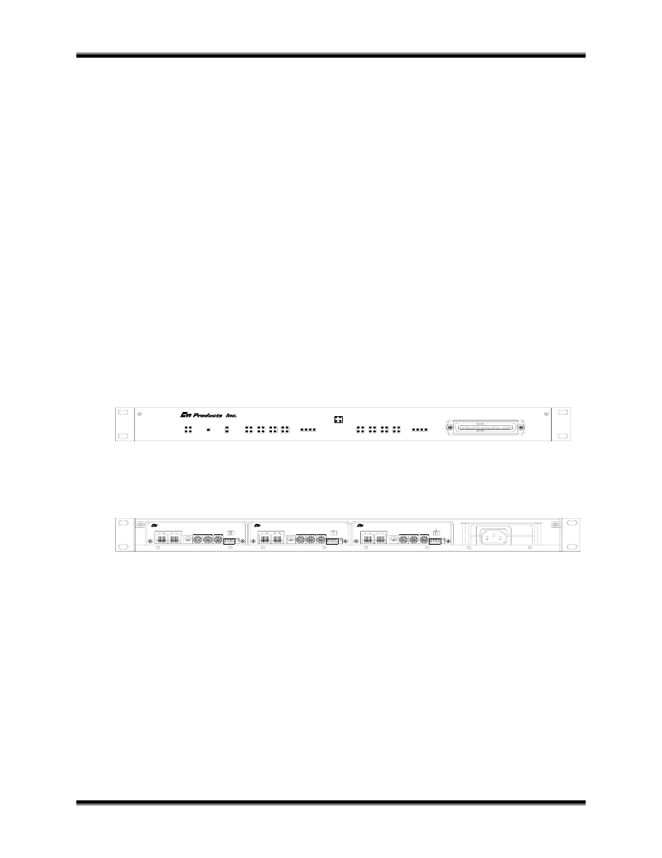
Figure 2 and Figure 3 show the OTAL Driver Assembly front and rear views. Figure 4 shows the top view.
PWR1 OK
PWR2 OK
RST
+5V
RESET
LINK 1
LINK 2
PTT A
PTT B
COR
OTAL
PTT A
PTT B
COR
OTAL
5
6 7 8
FAIL
FAIL
1 2 3
4
8
7
6
5
4
3
2
1
COR
OTAL
PTT A
PTT B
LED LEGEND
J1
LOCAL I/O
OTAL DRIVER
CB-61030-100 Front View
OTAL Outputs
Local PTT (PTT A) Inputs
Figure 2 – OTAL Driver Front View
CD-61030-100 Rear View
DC IN
IN
OUT
NETWORK
PRODUCTS, INC.
MODULE
GROUP
PWR
ACT
ERR
DC IN
IN
OUT
NETWORK
PRODUCTS, INC.
MODULE
GROUP
PWR
ACT
ERR
DC IN
IN
OUT
NETWORK
PRODUCTS, INC.
MODULE
GROUP
PWR
ACT
ERR
COR IIB
PTT IIB
OTAL CIB
Figure 3 – OTAL Driver Rear View
Introduction
6