Internal connections, Ptt iib to otal driver pcb, Otal – CTI Products OTAL On-the-Air Driver Assembly User Manual
Page 13: River, Nternal, Onnections
CTI Products, Inc.
OTAL Driver Assembly User Guide
I
NTERNAL
C
ONNECTIONS
PTT
IIB
TO
OTAL
D
RIVER
PCB
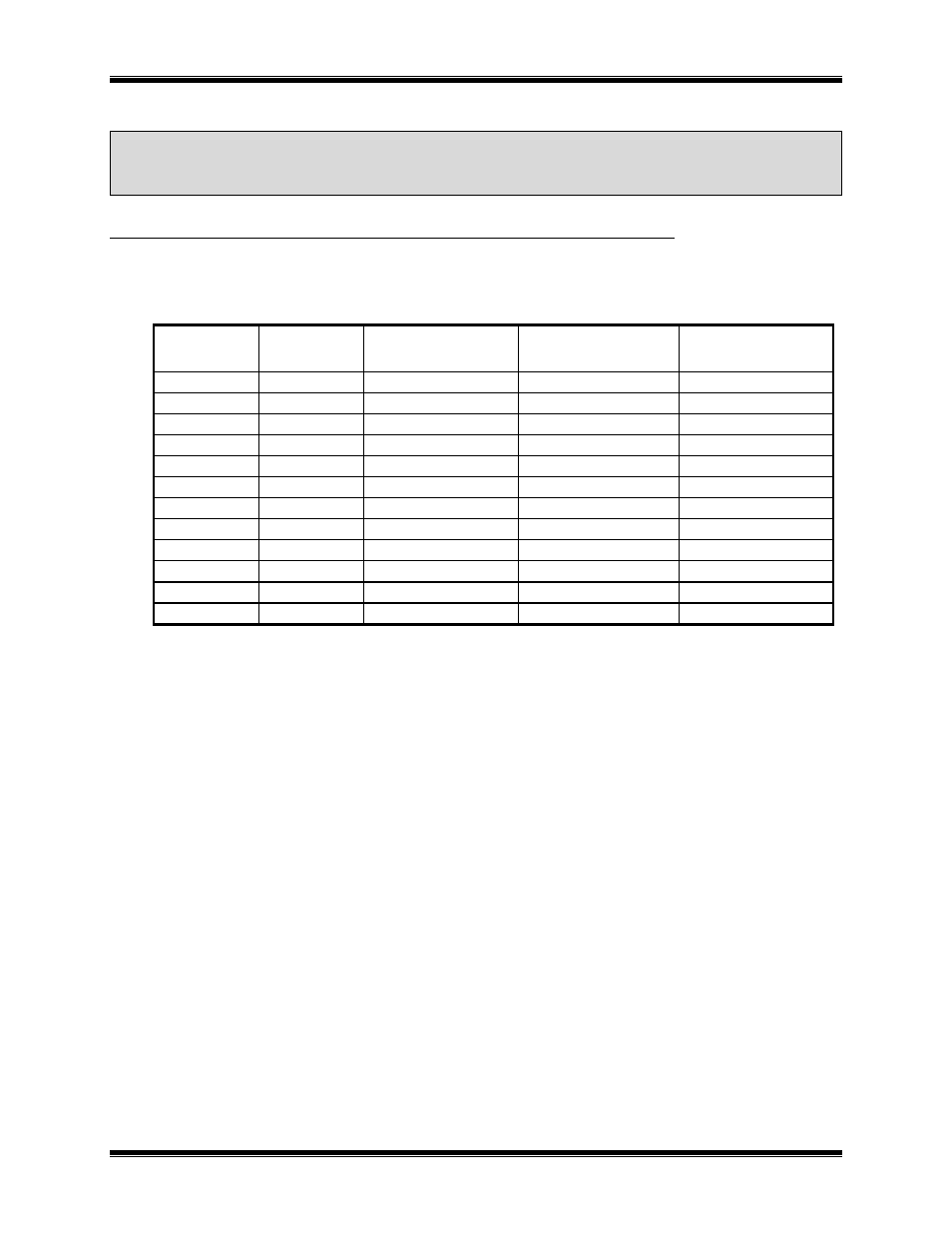
The PTT IIB is connected to J2 on the OTAL Driver board through a ribbon cable as follows:
PTT IIB J1
IIB I/O
IIB Function
OTAL Driver PCB
Connector J2
OTAL System
Function
1
Gnd Ground
1
Ground
4
I
Link Fail Enable
7
Ground
29
I
Link Fail Invert
8
Ground
30
O
Fail 8 / Link Fail
10
LinkUp1
19
O
Rx 1
37
PTT 1B
44
O
Rx 2
38
PTT 2B
12
O
Rx 3
23
PTT 3B
37
O
Rx 4
24
PTT 4B
6
O
Rx 5
11
PTT 5B
31
O
Rx 6
12
PTT 6B
18
O
Rx 7
35
PTT 7B
26
O
Rx 8
2
PTT 8B
All signals are active low.
The Link Fail Enable and Link Fail Invert signals are inputs to the IIB. They are read-only at power-up of the
IIB. Therefore, the IIB must be connected to the OTAL Driver PCB before it is powered up. Otherwise, the
Link UP signal will not be active.
Internal
Connections
13
- MCN RCD System Overview (46 pages)
- MCN RCD System Planner (53 pages)
- RCD Standard - Remote Comparator Display (2 pages)
- RCD Standard - Remote Comparator Display (119 pages)
- RCD Client-Server (2 pages)
- RCD Advanced Client-Server (169 pages)
- RCD Advanced Client-Server (2 pages)
- MCN Server 8000 (3 pages)
- MCN Server 8000 (232 pages)
- EXB Network Manager (48 pages)
- HIB-IP IP Interface (2 pages)
- HIB-IP IP Interface (36 pages)
- HIB-232 Serial Interface (2 pages)
- HIB-232 Serial Interface (19 pages)
- PCLTA PCI Interface (2 pages)
- PCLTA PCI Interface (33 pages)
- IIB Console Interface (2 pages)
- IIB Console Interface (26 pages)
- CIB Comparator Interface (2 pages)
- CIB Comparator Interface (40 pages)
- AIB AstroTAC Interface (2 pages)
- AIB AstroTAC Interface (19 pages)
- EXB-IM PSTN System Extender (4 pages)
- EXB-IP Ethernet System Extender (63 pages)
- EXB-IM PSTN System Extender (31 pages)
- GPIO General Purpose I/O Interface (3 pages)
- GPIO General Purpose I/O Interface (26 pages)
- GPIO-CVT Buffer/Logic Converter (2 pages)
- IOB I/O Interface (33 pages)
- CHIB CommandSTAR Lite Host Interface Module (22 pages)
- CCU Channel Control Unit (24 pages)
- CCU-2 Channel Control Unit (21 pages)
- RYB-8 Relay Board (2 pages)
- RYB-8 Relay Board (17 pages)
- Quad Router Panel (2 pages)
- OTAL On-the Air Terminal Board and Lamp (14 pages)
- DC Distribution Panel (9 pages)
- TSAM Transmitter Steering & Audio Matrix (2 pages)
- TSAM Transmitter Steering & Audio Matrix (97 pages)
- TIB TSAM Interface (2 pages)
- TIB TSAM Interface (24 pages)
- TurboVUi Solo Client Software (1 page)
- TurboVUi Solo Client Software (12 pages)
- TurboVUi Solo Client Software (16 pages)