Otal outputs, Otal, Utputs – CTI Products OTAL On-the-Air Driver Assembly User Manual
Page 11
CTI Products, Inc.
OTAL Driver Assembly User Guide
The Remote COR signals appear on the following pins of J1 of the remote COR CIB module as follows:
Remote COR CIB J1
Wire Color
CIB Function
OTAL System Function
1 Blu/Wht
Ground
Ground-Common
22
Org/Vio
Rx 1
COR 1 input
47
Vio/Org
Rx 2
COR 2 input
16
Blu/Yel
Rx 3
COR 3 input
41
Yel/Blu
Rx 4
COR 4 input
10
Slt/Red
Rx 5
COR 5 input
35
Red/Slt
Rx 6
COR 6 input
4
Brn/Wht
Rx 7
COR 7 input
29
Wht/Brn
Rx 8
COR 8 input
OTAL
O
UTPUTS
The OTAL outputs are opto-isolated solid state relays. They are active in the closed position. These outputs
appear on the last 8 pairs of J1 of the OTAL Driver Assembly as follows:
OTAL Driver Assembly J1
Wire Color
Signal
43
Yel/Grn
OTAL Ry 1+
18
Grn/Yel
OTAL Ry 1-
44
Yel/Brn
OTAL Ry 2+
19
Brn/Yel
OTAL Ry 2-
45
Yel/Slt
OTAL Ry 3+
20
Slt/Yel
OTAL Ry 3-
46
Vio/Blu
OTAL Ry 4+
21
Blu/Vio
OTAL Ry 4-
47
Vio/Org
OTAL Ry 5+
22
Org/Vio
OTAL Ry 5-
48
Vio/Grn
OTAL Ry 6+
23
Grn/Vio
OTAL Ry 6-
49
Vio/Brn
OTAL Ry 7+
24
Brn/Vio
OTAL Ry 7-
50
Vio/Slt
OTAL Ry 8+
25
Slt/Vio
OTAL Ry 8-
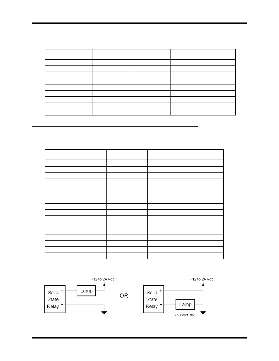
The solid-state relay outputs listed above are polarity-sensitive, and are current-limited to 0.5A. Typical lamp
connections are shown below.
Figure 5 – Typical Lamp Connections
Field
Connections
11