Indicators, 1 input and output leds, 2 pwr, err, act leds – CTI Products GPIO General Purpose I/O Interface User Manual
Page 13: Nput and, Utput, Output leds input leds
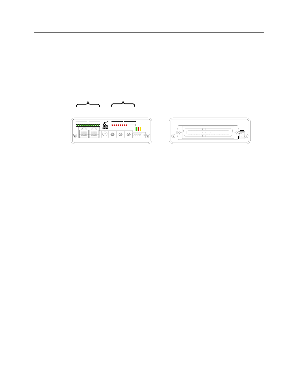
GPIO Hardware Reference
Indicators
CTI Products, Inc.
4. Indicators
4.1 Input and Output LEDs
The GPIO has LEDs to display the status of all installed inputs and outputs.
Status LEDs for inputs are green. Status LEDs for outputs are red. The following
shows a GPIO module configured with 12 inputs (on the left) and eight outputs
(on the right). LEDs will be lit when the input or output is active.
J1
E1 A
E1 B
GPIO-1208 Module
89
7
A
B
C
D
EF
01
23
4
5
6
89
7
A
B
C
D
EF
01
23
4
5
6
89
7
A
B
C
D
EF
01
23
4
5
6
1
2 3 4
ON
PWR
ACT
A
11 12
10
9
8
7
6
5
4
3
2
1
RESET
DC IN
OPTION
MODULE
GROUP
IN
OUT
NETWORK
SVC
ERR
B
1
2 3
4 5
6 7
8 9 10 11 12
Front View
Rear View
CA-80851-100
Output LEDs
Input LEDs
Figure 4 – Location of Indicators and Setup Switches
4.2 PWR, ERR, ACT LEDs
The GPIO has three additional LED indicators on the front panel.
PWR Continuously lit:
Sufficient power is present.
Blinking:
Voltage
is
low.
ERR 1 Blink:
Group:Module set to FF:F (Invalid address)
Continuously lit:
Other error (hardware or software)
ACT Lit:
Connected to a PC running MCNRCD software
68-12068-100
13