1 solid state relay option, 2 mechanical relay option, 3 magnetically-latched relay option – CTI Products GPIO General Purpose I/O Interface User Manual
Page 12: Olid, Tate, Elay, Ption, Agnetically, Atched
GPIO Hardware Reference
Inputs & Outputs
CTI Products, Inc.
3.1 Solid State Relay Option
The default setting for Solid State Relay output current is 1 A maximum,
resistive. For this setting, the relay on-resistance is 500 m-ohms. For DC loads
only, an internal jumper setting is available to allow 1.5 A maximum, with an on-
resistance of 150 m-ohms.
The maximum current stated above is for resistive loads only. For inductive
loads, the maximum current must be de-rated.
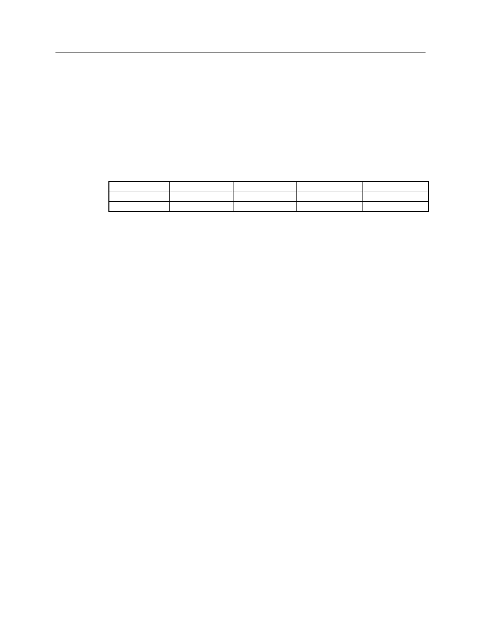
Jumper settings for Solid State Relay maximum load selection are listed in the
following table.
Load Type
Voltage (max.)
Current (max.)
On-Resistance
Jumper(s)
AC or DC
24V
1 A
500 m-ohms
B
Hi DC
24V
1.5 A
150 m-ohms
A & C
Table 3 – Loading Selection for Solid State Relay Option
3.2 Mechanical Relay Option
The Maximum Current rating of 1A listed in Table 2 is for resistive loads only.
For inductive loads, the maximum current must be de-rated.
3.3 Magnetically-Latched Relay Option
When these relays are changed to the Set mode, the Normally Open contact will
close, and the Normally Closed contact will open. When changed to the Reset
mode, the Normally Open contact will open, and the Normally Closed contact
will close.
Magnetically-latched relays will hold their state even when the power to the
GPIO module is off.
The Maximum Current rating of 1A listed in Table 2 is for resistive loads only.
For inductive loads, the maximum current must be de-rated.
68-12068-100
12