5 resolver alignment -36 – CONTREX CXB2040 User Manual
Page 38
8900 Zachary Lane N., Maple Grove, MN 55369 U.S.A.
35
6.5 RESOLVER ALIGNMENT:
Note:
CONTREX motors with built-in resolvers are factory aligned. Consult a CONTREX
applications engineer prior to attempting a resolver realignment. Failure to do so may void the warranty.
Note:
Consult a CONTREX applications engineer before aligning a non-CONTREX motor/resolver.
Some motor/resolvers require procedures other than that described here.
Note: Dip-switches S3-1, S3-2, S3-3 and S3-4 allow the converter to be operated in one of eight
modes. The first six modes set the number of motor "poles". One pole corresponds to one magnet, thus a
motor with two "north" and two "south" magnets has four poles. The number of electrical revolutions is
equal to one-half the number of poles. An electrical revolution refers to the arc-length the motor will
rotate when one complete sine-wave is applied. Therefore, a four-pole motor has two electrical
revolutions and requires two sine-waves to make one mechanical (shaft) revolution. The significance of
this is, any motor with more than one electrical revolution will have more than one electrical "index" (0
o
position), while there is only one mechanical index. From an electrical viewpoint, any index may be used,
however from a mechanical viewpoint, using a different electrical index may alter the mechanical index
by as much as 180
o
from its previous position. This will show itself as a change in where the encoder
index (channel Z) pulse occurs.
Note that the emulated encoder has an index per mechanical (shaft) revolution.
Of the remaining two modes, the INDEX is used to generate an index output and is used for resolver
alignment.
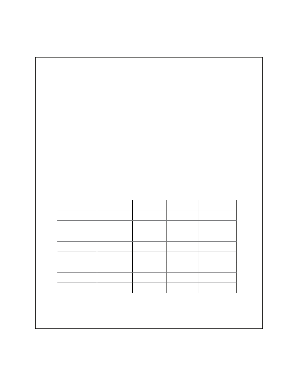
MOTOR:
S3-1
S3-2
S3-3
S3-4
2 POLE
ON
ON
ON
ON
4 POLE
ON
ON
ON
OFF
6 POLE
ON
ON
OFF
ON
8 POLE
ON
ON
OFF
OFF
10 POLE
ON
OFF
ON
ON
12 POLE
ON
OFF
ON
OFF
ZERO
ON
OFF
OFF
ON
INDEX
ON
OFF
OFF
OFF
CHAPTER 6: START UP AND CALIBRATION