3 servo loops – CONTREX CXB2040 User Manual
Page 16
8900 Zachary Lane N., Maple Grove, MN 55369 U.S.A.
13
CHAPTER 2: THEORY OF OPERATION
2.3 SERVO LOOPS:
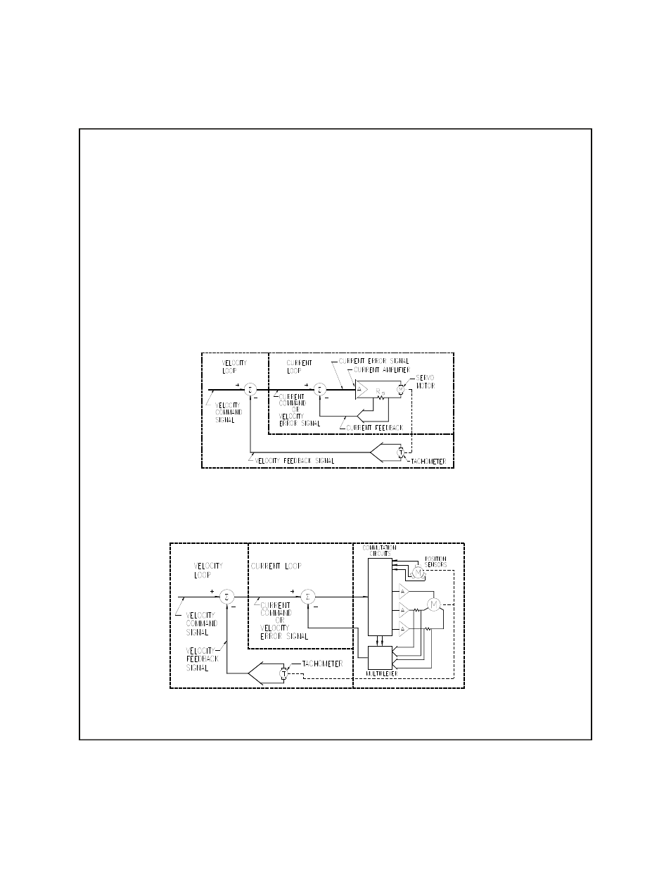
A basic velocity-mode servo-loop for a brush-type motor is shown in figure 2.2a. An external
controller commands a given velocity (RPM). The velocity-loop summing-amplifier compares this
command with the actual motor velocity, supplied by a DC tachometer on the motor shaft, and produces
an error voltage proportional to the difference between the actual and commanded velocity.
The velocity error is used to command motor current in the inner servo-loop. The current- loop
summing-amplifier compares the command current (velocity error) with the actual current in the motor
and produces an error voltage proportional to the difference between the actual and commanded current.
Finally, the current-error signal is used to produce an output (linear or PWM) to drive the motor.
The velocity loop may be bypassed, and an external current command fed directly to the current loop.
In this case, the external command signal controls the torque of the motor, rather than the velocity. This
is known as current-mode operation.
Figure 2.2a
Velocity-mode sevo loop for a brush-type motor
The servo-loops of a brushless amplifier (figure 2.2b) operate in much the same way, except there are now
three current loops, one for each phase of the motor.
Figure 2.2b
Velocity-mode sevo loop for a brushless motor