1 introduction, 2 driving dc servo-motors – CONTREX CXB2040 User Manual
Page 15
CXB1525 and CXB2040 MANUAL
8900 Zachary Lane N., Maple Grove, MN 55369 U.S.A.
12
CHAPTER TWO: THEORY of OPERATION
2.1 INTRODUCTION:
This chapter contains the basic control theory of how brush-type and brushless servo motors and
amplifiers operate. It also compares and contrasts the advantages and disadvantages of brushless and
brush-type motors and amplifiers to help you select which is best suited for your application. The
following is a summary of the topics:
The theory behind an amplifer driving DC servo-motors.
A comparison between brush-type and brushless motors.
A comparison between trapezoidal mode and sinusoidal mode.
The advantages and disadvantages of trapezoidal amplifier systems.
A comparasion between velocity mode and current mode.
Various kinds of velocity feedback.
Commutation using resolver.
Current mode in sine/resolver or trapezoidal amplifier vs two/three phase input current amplifier.
Protection circuits.
2.2 DRIVING DC SERVO-MOTORS:
The torque of any DC motor is proportional to motor current: the stronger the magnetic field, the
stronger the pull. Motor current may be controlled in two ways: linear and PWM (Pulse-Width
Modulation). Linear control is achieved by simply inserting a resistance in series with the motor. This
resistance is usually a partially turned-on transistor. The transistor is said to be in its "linear" region.
Linear amplifiers are simple, accurate, and effective. However, they are very inefficient and they generate
a lot of heat. Linear amplifiers are used when low electrical noise, high bandwidths (2KHz or higher) and
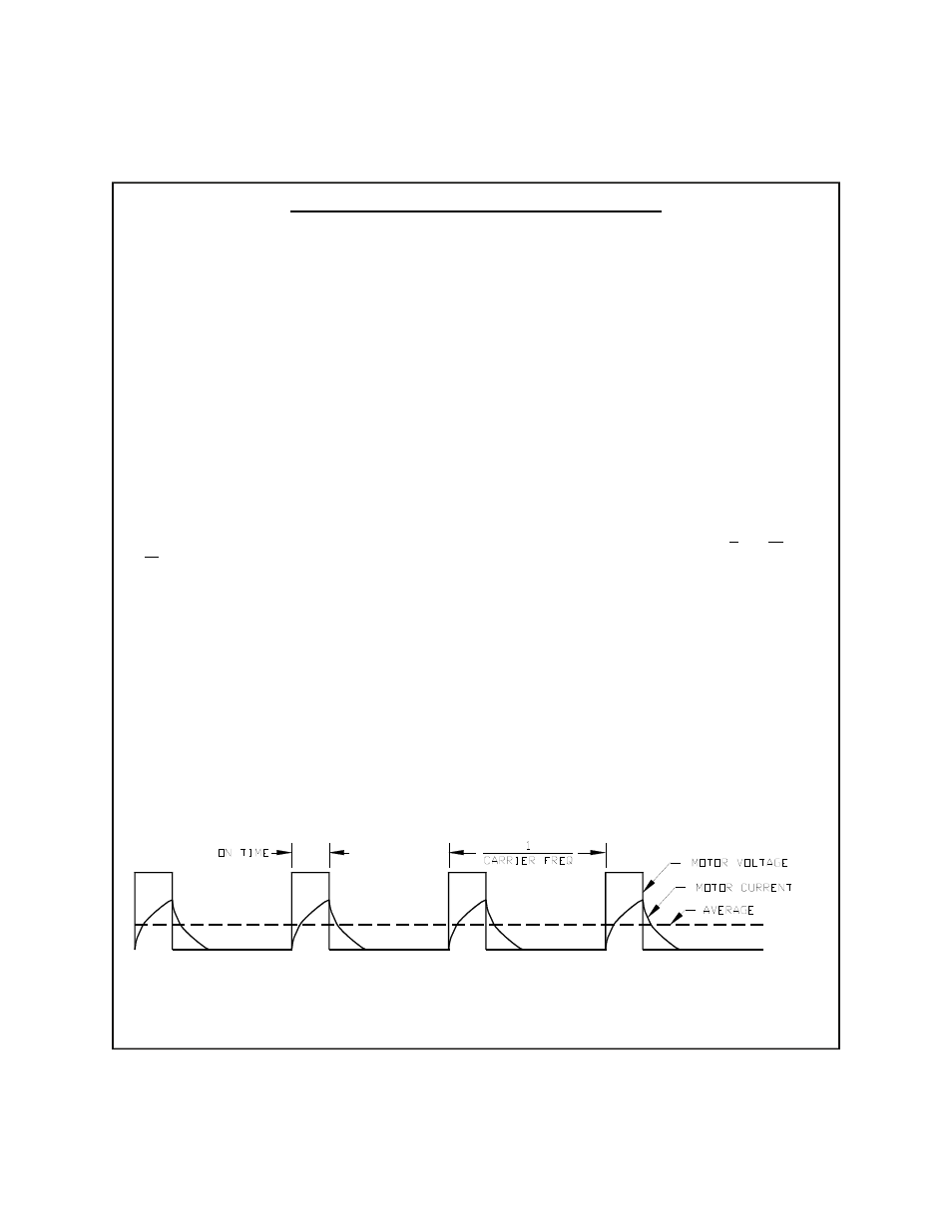
or low inductance (less than 1mH) motors are used. In pulse-width modulation the control devices
(output transistors) are rapidly turned full-on and full-off. The ratio of the on-time (the pulse width) and
off-time determines the average motor current. Refer to figure 2.1. For example: if the output is on 25%
of the time and off 75% of the time, the average motor current is approximately 25% of maximum.
A coil of wire, such as the windings of a motor, forms an inductor. Inductors resist changes in
current. This resistance to change, known as reactance, acts to dampen or average the high-current spikes
that would otherwise occur when the output devices are on. In fact, if motor inductance is low, external
inductors may have to be added in series with each motor lead to ensure proper operation.
Figure 2.1
Pulse Width Modulation Waveform